Electro Tech is an online community (with over 170,000 members) who enjoy talking about and building electronic circuits, projects and gadgets. To participate you need to register. Registration is free. Click here to register now.
Welcome to our site! Electro Tech is an online community (with over 170,000 members) who enjoy talking about and building electronic circuits, projects and gadgets. To participate you need to register. Registration is free. Click here to register now.
I have audio coming out of a PIC DAC as a differential output (it is giving me both the positive and the negative). I need it in single-ended form (one wire referenced to the circuit's ground).
It's not positive and negative. It's above and below a positive bias voltage (the dsPIC does not have a negative voltage supply). Just use a difference amplifier or differential amplifier with a gain of 1 if you want to re-reference the signal to ground rather than the bias point.
It's not positive and negative. It's above and below a positive bias voltage (the dsPIC does not have a negative voltage supply). Just use a difference amplifier or differential amplifier with a gain of 1 if you want to re-reference the signal to ground rather than the bias point.
So are you saying I could plug the dsPIC DAC output right into, say, an LM4808M [**broken link removed**] to drive headphones?
I guess the main thing I'm trying to do with this DAC output is just drive headphones. Right now, if you plug the headphones right into the DAC1RN/P, the sound is kind of low (even when audio is cranked up).
The 33F DAC was designed to drive an audio amplifier. It does not have enough power to drive headphones directly since it is a data processing device, not a power device. You would use the bias output voltage of the DAC IN+ for the IC.
Just curious, were you using DC block capacitors when directly connecting the DAC to the headphones?
Is this a differential PWM output DAC? If so, I have several ways of helping you. Do you want a PWM amplifier (high efficiency but complex) or a simple linear amplifier (inefficient, lower power, but easy way to drive headphones)? Remember you should be lowpassing the signal if it is a PWM output.
The 33F DAC was designed to drive an audio amplifier. It does not have enough power to drive headphones directly since it is a data processing device, not a power device. You would use the bias output voltage of the DAC IN+ for the IC.
Just curious, were you using DC block capacitors when directly connecting the DAC to the headphones?
The DAC1RP is coming out biased at 1.7 volts (Vdd/2). If I can remove that bias (bring it down to 0) and give it some current to drive headphones, I'd be golden....
Is this a differential PWM output DAC? If so, I have several ways of helping you. Do you want a PWM amplifier (high efficiency but complex) or a simple linear amplifier (inefficient, lower power, but easy way to drive headphones)? Remember you should be lowpassing the signal if it is a PWM output.
Those DC blocking capacitorson the output of the audio amplifier datasheet you attached ARE what remove the bias. For more current you just use an op-amp buffer or amplifier. If you remove the bias BEFORE you amplify it then you need a +/- power supply and op-amp. THat's why the bias and DC block capacitors are there...makes it easier to use.
Nevermind! Got it!! The outputs had to be switched. I knew I saw somewhere on the Microchip forums that the N/P for the DACs had to be swapped. Thanks for the help everyone
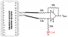
You used a differential amplifier circuit that uses a positive and negative supply because the inverting input to the input resistor was biased at the PIC's reference voltage but the non-inverting input was biased at half the reference voltage. Then the output of the opamp idled at 0V. It cannot swing to a negative voltage without a negative supply.
My circuit uses a capacitor so that the output DC voltage of the opamp is at the reference voltage and can swing positive and negative from there.
This site uses cookies to help personalise content, tailor your experience and to keep you logged in if you register.
By continuing to use this site, you are consenting to our use of cookies.

")