Continue to Site

Welcome to our site!

Electro Tech is an online community (with over 170,000 members) who enjoy talking about and building electronic circuits, projects and gadgets. To participate you need to register. Registration is free. Click here to register now.

  • Welcome to our site! Electro Tech is an online community (with over 170,000 members) who enjoy talking about and building electronic circuits, projects and gadgets. To participate you need to register. Registration is free. Click here to register now.

differential op amp circuit?

Status
Not open for further replies.

prh

New Member
Hi all
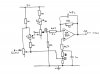
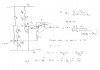
I'm hoping for a bit of help with the circuit shown.
Its 23 years since I last studied op amp circuits and the old grey matter going a bit soft so I hope you can help.
The circuit is part of a control system for positioning a hydraulic ram. R3 and R4 are trimmers to set max and min up/down position of the ram designed to be set to R3=10 ohm & R4=25 ohm. The control variable resistor is moved by a lever the operator moves, the sensor variable resistor (identical to the control one, both 5 to 190 ohm) is mechanically linked to the ram and provides position feedback to the circuit. The output of the circuit is supposed to vary between 0.4 and 5v. The output is supposed to be 2.5v when both variable resistors are in the same position and the ram is motionless. The output is fed into some comparitor circuits that produce up/down signals to move the ram, this bit of the circuit I understand. It's this bit of the circuit I can't analyse properly.

How I see it at the moment is (and I am probably wrong):
It's some sort of differential amplifier.
Gain is R1/R2 = about 3
The voltages at points A & B are basically set by the resistor chains, which act as voltage dividers.
The control variable resistor varies voltage B from 1.66 to 2.5v.
The Sensor variable resistor varies voltage A from 2.5 to 1.25v.
There are a few capacitors but this is basically a DC circuit.

Any help in analysing / understanding this better or anyone seen the same circuit used elsewhere gratefully appreciated.

(sorry about the diagram quality)

prh
 

Attachments

  • diffamp.jpg
    diffamp.jpg
    64.6 KB · Views: 1,750
I haven't got time to study that circuit at the moment but it doesn't appear to be a standard differential amplifier, it looks moke like a normal inverting amplifier with a capacitor to intoroduce another low frequency pole.

There are plenty of differential amplifier tutorials available on Google.

**broken link removed**

You could add the capacitors in parallel with the 0V and + input resistor and the - input to output feedback resistor.

I'm sorry I didn't understand, what gain do you require?


https://www.google.com/search?clien...ifier+op-amp&sourceid=opera&ie=utf-8&oe=utf-8
 
There appears to be too many parts. I suspect that you could do it with less.

You basically need a Wheatstone Bridge circuit so that it is balanced when the Ram position matches the setting of the control variable.

I don't have time to draw a suggestion at the moment, will do it later.
 
How I see it at the moment is (and I am probably wrong):
It's some sort of differential amplifier.
Gain is R1/R2 = about 3
The voltages at points A & B are basically set by the resistor chains, which act as voltage dividers.
The control variable resistor varies voltage B from 1.66 to 2.5v.
The Sensor variable resistor varies voltage A from 2.5 to 1.25v.
There are a few capacitors but this is basically a DC circuit.
I haven't checked the voltages you mentioned, but basically you have it right. The difference between the two input voltages is output as an "error voltage" to tell the RAM via the comparaters which way to go. The 47Uf slows the circuit down enough so that the RAM doesn't "hunt"...

There appears to be too many parts. I suspect that you could do it with less.
That's what I thought at first, but once I read his post more carefully I realized that the "extra" POTs were trimmers for the feedback and control POTs.
 
What i can see is Yes it is a differential amplifier and basically a DC circuit. The capacitors are here to suppress noise / spurious signals to provide stability to the circuit. The circuit is easy to analyse with simple voltage divider rules. I think you have analysed correctly.

Aily
 
Here is how I would do it.

It is a diff amp with an offset adjustment (Rx) so that you can set the output to 2.5V when V1 = V2.

V1 & V2 are generated by the Control and Sensor pots respectively.

Connect one end of the Control pot to + (via a resistor if you need to limit the range) and the other end to gnd (also via a resistor if necessary)

Do the same with the Sensor pot.

I have used McMillman's Theorem to derive the expression for Vo.

Note that R1//R2 means R1 in parallel with R2.

Make R1 at least 10 times greater than the Sensor pot value so that adjusting the pot does not alter the situation much.

Make R3 = R1 and R2 = R4//R5 so that C1 = C2.

By "+" I mean the positive supply voltage (I don't have the internet open at the moment so I can't look at your circuit)

If you have any questions, just ask.

Edited to correct an error.
 

Attachments

  • Diff Amp 1.gif
    Diff Amp 1.gif
    26.9 KB · Views: 906
Last edited:
Thanks all for the feedback its much appreciated.
Just to make things clear, this is part of an actual circuit that has been in use for 20 years or so. I have come across it recently doing some charity work and im trying to understand it as well as i can.
Your replys give me confidence that im roughly on the right track. I agree that its not the tidyest of circuits and could probably have been implemented better but this is whats there.
The bit i cant fathom is a formula for V out in terms of the control and sensor variable resistor values but thats my problem.
I realise the capacitors shown are really there just to deal with transients when the variable resistors are moved.
The comparitor circuits (after V out) compare V out with 2 and 3 volts (more resistor voltage dividers) to create either an up or down or no change signal.
Maybe looking at V out in terms of the control and sensor variable resistor values isnt the way to go.
Im glad its not an AC circuit cos then i would be into poles and zeros and well stretched beyond what i can remember about mr Laplace

Thanks all prh
 
prh said:
Thanks all for the feedback its much appreciated.
Just to make things clear, this is part of an actual circuit that has been in use for 20 years or so. I have come across it recently doing some charity work and im trying to understand it as well as i can.
Your replys give me confidence that im roughly on the right track. I agree that its not the tidyest of circuits and could probably have been implemented better but this is whats there.
The bit i cant fathom is a formula for V out in terms of the control and sensor variable resistor values but thats my problem.


Code:
The trick is to calculate the voltages with the Op amp disconnected 
and then calculate what the Op amp will do when the connections are restored.  
It is easier to do the calculations if the resistors going to the + & - inputs 
of the Op amp are at least 10 times greater than the pot resistances.  
Then the loading effect can be ignored to a reasonable 
dergee of accuracy.

I realise the capacitors shown are really there just to deal with transients when the variable resistors are moved.
The comparitor circuits (after V out) compare V out with 2 and 3 volts (more resistor voltage dividers) to create either an up or down or no change signal.
Maybe looking at V out in terms of the control and sensor variable resistor values isnt the way to go.
Im glad its not an AC circuit cos then i would be into poles and zeros and well stretched beyond what i can remember about mr Laplace

Thanks all prh

See the insert above.
 
Last edited:
Ok got it sorted now once i realised i needed to equate Vb to V+ And hence V-. I could then get the current i in R1 and R2 and hence work out a value for Vo .
I made a spread sheet with all these values in and it actually works, Vo is just about 2.5 v when the values of VR1 and VR2 are the same.
Ive attached the analysis.
What i can say is i would never have come up with this circuit if i had been designing it.
Thanks for your time and input Len

Paul
 

Attachments

  • analysis.jpg
    analysis.jpg
    93.9 KB · Views: 917
I reached the same expression using McMillman's Theorm.

Code:
Vo = (R1 + R2)Vb/R2 - R1 Va/R2

For R1 = 15k and R2 = 4.7k

Vo = 4.19 Vb - 3.19 Va
 
Can you point me towards McMillman's Theorm somewhere, i dont remember anything by that name as such

prh
 
Status
Not open for further replies.

Latest threads

Back
Top