Continue to Site

Welcome to our site!

Electro Tech is an online community (with over 170,000 members) who enjoy talking about and building electronic circuits, projects and gadgets. To participate you need to register. Registration is free. Click here to register now.

  • Welcome to our site! Electro Tech is an online community (with over 170,000 members) who enjoy talking about and building electronic circuits, projects and gadgets. To participate you need to register. Registration is free. Click here to register now.

Differential amplifier

Status
Not open for further replies.

spintinas

New Member
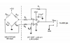
Hello, I have a problem with differential amplifier. I use LMC6484 (https://www.ti.com/lit/ds/symlink/lmc6484.pdf) op amp to project differential amplifier (schematic in the picture). Resistors values are R1=R3=100k and R2=R4=1k, so theoretically gain should be about 100. My object for this project is to amplify signal from Honeywell pressure transducer (https://stevenengineering.com/tech_support/PDFs/31DTMAIN.pdf) which voltages are about 0-30mV, to voltages for adc. I connect this circuit on breadboard and connect my pressure transducer signal+ and signal- wires to differential amplifier + and - inputs. Voltage between pressure transducer data pins, when there is no pressure is about 30mV, and in differential amplifier output i get 4,6V, but when I apply pressure to transducer and transducer output voltage is increasing, there is no change in amplifier output - still 4,65V. Maybe someone know solution for this problem?
 
Look like your at Maximum Output from the Op-Amp.
You need a NULL Pot to Offset that 4.6 Volts when at No Pressure.
 
Here its my schematic.
 

Attachments

  • differential amp.png
    differential amp.png
    44.9 KB · Views: 144
That circuit is extremely sensitive to the slightest difference between R2 and R4 resistance values, and between R1 and R3. The pairs of resistors have to be matched to within 0.01%, very difficult to do.

Rather than screw with matched resistors, most people just buy an "instrumentation" amplifier, which is manufactured with matched resistors in the first place.
 
Hello dear colleagues, i have some questions for you about signal filtering. I want to project daq for my pressure transducer. Firstly, I have a signal from transducer (voltage about 30-60mV), then i design differential amplifier with gain of 20, and the output voltages transducer now are 500mV-1,1V, but when get a signal in osciloscope, there are a lot of noise. So, the question is, what filter is best to use for this type of signal (pressure transducer), also I want to know when it is better to filter signal? Before amplification or after differential amplifier?. I read some information on the internet and I understood, that one of the option for this situation is passive low pass (RC) filter, but I didnt know what value of cutoff frequency should be, and also low pass filter will attenuate my useful signal. So, guys, I would be thankful if you suggest some solutions.

Transducer datasheet: http://technel.com/Files/AB-HP.pdf

Differential amp schematics is attached, i use LM324, instead LMC6484.
 

Attachments

  • differential amp.png
    differential amp.png
    44.9 KB · Views: 130
i didn't know what frequency
What are you measuring?
How often does it change?
How often do you measure it?

Example: A automotive gas tank is measured with a 20 second filter. Gas moves in the take.
Example: Oil pressure in a car has a response time more like 1 second.
 
I measure a pressure from blood pressure pump. I manualy push the pump to 400mmHg and then i release the air with the same intervals of 20mmHg. From 400 mmHg to 0 mmHg (400-380-360-340-...-0). Later i use real blood pressure monitor, so I want to get clear relationship between pressure and voltage.
 
blood pressure pump
So can you live with a meter that gets to 60% of the reading in 1 second? That is probably slow for the pressure going up but OK for going down.

You could try a 10hz filter (0.1 second) and see if the noise if good.
You can do the simple filter I showed in post #2 and add more filtering in software. (read 10/second and average the last 10 readings)
Okay, i will try your suggestion, but is this filter dont affect amplitude of my amplified signal? After amplification, voltage is in range of 500mV-1.1V. After filtering, I want, that output voltage range remain the same.
 
If you have a 10hz filter then any signal that is slow will be amplified 20x. But signal/noise at 60hz will be made smaller.
Your pump is slower than 0.1 second so any change it makes will come through just fine. There is probably noise at 1khz and for certain noise at the power line frequency. This should be pushed down. The oscilloscope sees noise up to 20,000,000 cycles/second. That is all noise and needs to be filtered out.
 
You did not describe the noise. Hum is a low frequency that is usually 50Hz or 60Hz electrical interference picked up by ordinary wires acting like antennas instead of using shielded audio cable. Hiss and rumble are caused by using cheap old opamps like the LM324. High resistor values also cause hiss. When the telephone was inverted the hiss and rumble from old electronics was terrible so they filtered away all the important low and high frequencies of speech.
 
Also, if you will be sampling the pressure using an ADC, you need to learn about anti-alias filtering.
 
but exactly i didn't know what frequency.
But you can determine it instead of just saying you don't know and expecting us to guess.
You have an oscilloscope.
Look at the noise and change the sweep speed in steps from low (10ms/div) to high (1us/div) to see if you can see any particular frequencies.
If so, measure the period and invert that value to get the frequency.
If the signal looks essentially the same at all sweep speeds, then its likely random noise.
 
Why? There should not be any signal in his blood pressure reading that will cause troubles.
If his amplified pressure reading is contaminated with high frequency noise, then he either has to sample often (>2X the highest noise spectural component), or he has to filter (call it either a "noise" filter or an "antialiasing" filter), and then he can sample at a lower rate...
 
Status
Not open for further replies.

Latest threads

New Articles From Microcontroller Tips

Back
Top