Continue to Site

Welcome to our site!

Electro Tech is an online community (with over 170,000 members) who enjoy talking about and building electronic circuits, projects and gadgets. To participate you need to register. Registration is free. Click here to register now.

  • Welcome to our site! Electro Tech is an online community (with over 170,000 members) who enjoy talking about and building electronic circuits, projects and gadgets. To participate you need to register. Registration is free. Click here to register now.

Diagnosing / repairing problem with charging of a Li-On 14.8v battery

Status
Not open for further replies.

Myrd

New Member
Hello friends!

I have a cordless vacuum that has recently stopped being able to charge its battery.

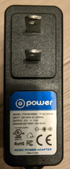
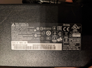
I believe this started happening after I accidentally plugged it into the wrong A/C adapter that had the same plug. (I plugged it into a laptop 19.5v adapter whereas the vacuum's adapter is 19v).

I thought this may have damaged the battery, so I ordered a replacement battery, this one:
https://www.aliexpress.com/item/1005003359507022.html?spm=a2g0s.12269583.0.0.396042b87o645X

The original battery was also a 14.8V "18650" battery, though with a lower mAh rating. The new battery worked well on its initial charge, but exhibited the same charging problem.

When I plug in the vac, it does indicate a charging light and eventually after some time, changes to the "charged" color. However, as soon as you start using the vacuum, it indicates that it has low power and turns off. I assume it is actually low power, since it was able to work fine when the battery had its charge from the factory.

I hooked up the AC adapter to a kill-a-watt and while charging, it's reading a 0.5 amp of power, which seems a bit low (although the adapter says it's rated for 0.8amp), but I assume this means that power is actually flowing.

At this point, I assume the problem must be with the charging electronics - perhaps these were overloaded when hooked up to the laptop's AC adapter. Is there a way to confirm that? If so, is it feasible to repair - e.g. by changing the circuit?
 
Last edited:
Are your ac adapter are both dc output?
Are the the same polarity? Positive and negative?
If u used one with reverse polarity then you may of damage the charging circuit.
Maybe send us a picture of adapters and charging circuit circuit board.
We are just blind mice on the other side of the web.
 
It's unlikely that 19.5V will damage something expecting 19V. It's more likely the wrong polarity.
Look for this symbol on your power adapters,
polarity.png


This indicates that the center pin is positive. If yours are different or the laptop is AC (very unlikely) then that is the problem.

Mike.
 
Thanks for the replies.

Here are the pics of the two adapters. I can open up the vacuum again tomorrow to take a pic of the charging circuitry.

It looks like the polarities are the same. The 19.5v / 7.7 A adapter is the laptop one.

The other AC adapter which is the one that worked perfectly for the vacuum is actually labeled 21V and 19V-22.5, not exactly sure why. It was a replacement AC adapter labeled specifically for this model vacuum, which theoretically should be 19V (e.g. similar to https://www.amazon.com/Holife-HM036-HLHM036BWUS-Power-Supply/dp/B078SMBGSG).

So if it's not the polarity, what else could it be? The main difference between the adapters is the much higher current - but would this ever matter? e.g. perhaps it won't supply 19.5v if the current is much lower - or perhaps the vacuum was trying to pull more current than it could handle?

1650426890473.png


1650426899834.png
 

Attachments

  • 1650426780465.png
    1650426780465.png
    529.9 KB · Views: 206
  • 1650426799333.png
    1650426799333.png
    2.1 MB · Views: 198
Voltage is not a problem and the polarity is correct.

However the charger is only rated at 0.8A output, while the laptop power adapter is rated at several amps; it could be that a high current switch-on surge has damaged some part of the electronics?

Was the laptop charger already turned on when you plugged it in?

What make and model vac is it, and can you provide photos of its circuit board, both sides in good detail?
 
OK, here are the photos of the circuit board:
1650466227017.png

The bottom left two wires go to the charging port, the middle two wires go to the battery and the right white/blue wires go to the vacuum motor.

Here's the other side, which has the switch and LEDs:
1650466448207.png


The laptop charger was plugged in when I accidentally plugged the vac into it and I didn't realize it was the wrong charger (so I let it "charge" on it for a while).

The vacuum model is the HoLife HLHM036BWUS.
 
OK, it looks like the power circuit for charging is from charger positive through an input polarity protection diode (bottom), a surface mount power FET, then another diode to prevent the battery feeding back to the charge circuit.

The transistor appears to be one of these:

The diodes:

With the battery and charger connected, measure the voltage from battery negative to the top of the lower left diode, and the left end of the upper diode?


VacBoard_marked.png
 
Thanks, I'll try that tonight.

Just to be clear, you'd like me to take a multimeter and do two DC voltage measurements (with everything hooked up to the charger):
1. Connect to the battery's black wire and to the soldering above the bottom left SS34 part indicated in red.
2. Connect to the battery's black wire and to the soldering left of the top right SS34 part indicated in red.

Just to make sure, since I'm a noob at this, the multimeter should be connected in parallel to the existing circuitry? (I've only used it in serial - e.g. to measure a battery or outlet.)
 
OK, please now measure the battery positive voltage, the left of the upper diode again, and also the voltage at the upper left pin of the transistor? Again, with battery and charger power.

The repeat reading is in case the battery voltage has changed slightly since the last one.

You are still reading across or between two points in the circuit, no different to measuring the voltage on a battery.

For info, a "series" connection would be where you temporarily replace or substitute a connection with the meter, usually on a current range, to measure the current that would be flowing through the wire you replaced.

On current ranges, the meter is effectively a dead short so current can flow through without the thing you are testing being affected by substituting the meter - so you never use it on a current range for such as we are doing - it would short the charger or battery and cause damage to both the board and the meter!

On voltage ranges, most digital multimeters are equivalent to a ten million ohm resistor, so can be connected to most things without influencing the circuit being tested.
 
OK, please now measure the battery positive voltage, the left of the upper diode again, and also the voltage at the upper left pin of the transistor? Again, with battery and charger power.

The repeat reading is in case the battery voltage has changed slightly since the last one.

Sorry, I want to make sure I am super clear on the instructions - I don't want to fry something accidentally.

Can you confirm you want me to take these three measurements:
1. The "battery positive voltage" - do you mean just the voltage of the battery on its own?
2. The "left of the upper diode again" - this is the repeat of measurement 2 from before?
3. The "voltage at the upper left pin of the transistor" - just to be clear, this would be from the battery negative to that pin?
 
All the measurement voltages are referenced (where the meter negative lead is connected) to battery negative, with battery and charger connected & charger powered.

The battery positive reading is from where the battery positive lead connects to the circuit board; = the right side of the upper diode.
Yes, and repeat the reading on the left side, as it's possible the battery voltage has changed over a few hours and the difference between those two readings above is probably quite small; too large or too small indicate a fault...

And yes correct for the transistor pin.

Also make sure the charger voltage (around 21V) is present at the bottom of the left diode, just to be certain everything is connected correctly; if it's not, the other readings are meaningless.
 
battery positive reading (right side of the upper diode): 14.4v
left of the upper diode: 14.6v
upper left pin of the transistor: 14.5v
bottom of the left diode: 21.4v
 
OK, I believe the transistor has blown. It has something around 6 - 7V between gate and source which should mean it's ON resistance is around 40 milliohms, from the data.

The battery should be charging - but it's not, so the transistor appears to be dead.

I cannot find the original ones, but these look to be a drop-in replacement, and cheap:
 
Last edited:
Thanks! Just to confirm, it's just a single part that needs to be changed? The rest of the circuit is fine - or we don't know yet?

And just so I understand, it's a FET, so its purpose is to control how much current flows. Voltage is applied to the gate (top left pin) to control how much current flows from source (bottom left pin) to drain (right pin).

We measured voltage at the Gate, so that's the "voltage applied" to control the current. So the hypothesis is it's not letting the current flow to the battery?

When you mention it's 7V between gate and source, I guess it's based on 21.4 - 14.5? Can you help me understand the diagnosis that the transistor has blown from this?
 
When you mention it's 7V between gate and source, I guess it's based on 21.4 - 14.5? Can you help me understand the diagnosis that the transistor has blown from this?
You can imagine a FET as very roughly like a variable resistor (between source and drain), controlled by the voltage between the source and gate terminals.

With no voltage, the resistance is near infinite, open circuit. With enough voltage, which depends on the device, the resistance drops to a low value, anything from one or two ohms to a few milliohms, again depending on the device.

The one in your circuit should be down to around 40 milliohms with 7V on the gate, so near a dead shot - and there should be virtually no voltage between source and drain, so the charger positive is in effect being connected directly to the battery, via the two diodes.


It's not a sophisticated charge control circuit, it has no current sensing anywhere, just the FET as an on-off switch to connect or disconnect the charger. It must rely on the charger being incapable of providing enough current to damage anything.

The laptop power unit has no such restriction and could deliver way more current than the transistor could stand when it switched on, so it popped...

If you look at the graph at the bottom left of page 3 in the transistor data sheet, it shows the typical resistance vs gate voltage for that specific device:


I have a couple of work lights that has exactly the same type of failure - they came with chargers that could only give half an amp, but they used USB connections like phones etc. so should have been OK to connect to any normal USB power source.

The designers apparently did not think of that, and did not include any current regulation. The charge circuits in each failed instantly when I used my normal multi output USB power unit, that I use for phones and tablets. The charge switch in the lights was only rated 0.8A, so virtually any recent USB power unit would blow them...
 
Thanks! So just so I understand, because the transistor should result in a 40 milliohms resistance per the spec assuming it's working correctly, we would expect the battery to be charging properly (because that resistance should let enough current through). And since the battery doesn't charge, then we suspect it's not actually providing that resistance and is instead a very high resistance such that no current is really making it to the battery? Do I understand that right?

One other question - the circuit has LEDs to indicate when the battery is charging or when it gets fully charged. The fully charged LED does light up after having it connected to power for a while (even when the battery doesn't get charged). How come? What's the mechanism by which it "senses" the charge and why is it wrong? Is it also related to the same transistor?
 
And since the battery doesn't charge, then we suspect it's not actually providing that resistance and is instead a very high resistance such that no current is really making it to the battery? Do I understand that right?
Yes, spot on.
If the FET was switching on properly, with 40 milliohms and the charger rated at less than an amp, there should be less than 0.04V between across the transistor, which connects to the inner ends of the diodes.

No idea on the LED... I can only guess that the charger control part of the device has some kind of time limit included as an extra over-charge protection, or in case the battery is not quite reaching the expected full charge voltage??
 
Status
Not open for further replies.

Latest threads

New Articles From Microcontroller Tips

Back
Top