throbscottle
Well-Known Member
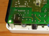
One of our ethernet over mains Devolo dLAN 200 AVdesk MT:2091 has developed a fault which looks like a low psu output. The lights on the front come on, but dim, and it doesn't show up on the network.
Mains plugs straight into the box for power and network to other devolo's, rj45 for connected device.
I'm kind of investigating and writing as I go along, so sorry if it's a bit disjointed...
The voltages coming out of the psu are: 1.2, 3.3, 12.2. I'm wondering if that 1.2v is supposed to be 5v, since it's smoothed by a 1000uF 10v cap. What does anyone think?
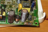
Theres no sign of swelling electrolytics and the semiconductors I can get to seem ok.
One huge symptom is a resistor on the primary side has been getting very hot, pcb is quite badly scorched. However the resistor is ok. It is connected in series with a capacitor not sure what type - large value ceramic perhaps, which measures ok. I don't understand what could cause this overheating though.
Switching chip gets warm. I notice the resistor doesn't get especially hot now, implying something was failing when it got hot, has now failed.
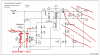
I lifted the schematic from the chip's datasheet, it's mostly similar to what's on the board. I added in the overheating resistor and series capacitor. Snubber perhaps? The point where they are connected doesn't appear to go anywhere else. The resistor is 470R, capacitor is unmarked but gives a slight kick on my meter.
The schematic is only to show the primary side - can't see what's going on with the secondary except it's a tapped winding with some hefty rectifiers 1N5822, and a smaller one, SB160 I think, though it's partly the same - I think the extras on the board are just voltage taps.
There's what appears to be a 6 leg NPN - ZXT10N20DE6T, in series with the 1.2v line, which is also fine. C~1.4v, E~1.2v, B~1.9v - looks like a classic series pass element. The collector voltage should be higher though.
If you look at the recommended layout on the TNY266PN's datasheet, it's very similar.
So should I start pulling electrolytics, even though they seem ok? Or should I be looking for something else drawing extra current?
Plan A so far - cut the lead of the rectifier (with 1.4v coming out) and connect a separate capacitor, see what the voltage is. Sound like a good plan to anyone? If it's 5v at least I'll know it's being pulled down.
(still looking up chips to try and identify what voltages are definitely required.)
Oh and it's a 6 layer board - it's got layer numbers in it.
Datasheet for smp chip: https://www.datasheetarchive.com/TNY266PN-datasheet.html
Mains plugs straight into the box for power and network to other devolo's, rj45 for connected device.
I'm kind of investigating and writing as I go along, so sorry if it's a bit disjointed...
The voltages coming out of the psu are: 1.2, 3.3, 12.2. I'm wondering if that 1.2v is supposed to be 5v, since it's smoothed by a 1000uF 10v cap. What does anyone think?
Theres no sign of swelling electrolytics and the semiconductors I can get to seem ok.
One huge symptom is a resistor on the primary side has been getting very hot, pcb is quite badly scorched. However the resistor is ok. It is connected in series with a capacitor not sure what type - large value ceramic perhaps, which measures ok. I don't understand what could cause this overheating though.
Switching chip gets warm. I notice the resistor doesn't get especially hot now, implying something was failing when it got hot, has now failed.
I lifted the schematic from the chip's datasheet, it's mostly similar to what's on the board. I added in the overheating resistor and series capacitor. Snubber perhaps? The point where they are connected doesn't appear to go anywhere else. The resistor is 470R, capacitor is unmarked but gives a slight kick on my meter.
The schematic is only to show the primary side - can't see what's going on with the secondary except it's a tapped winding with some hefty rectifiers 1N5822, and a smaller one, SB160 I think, though it's partly the same - I think the extras on the board are just voltage taps.
There's what appears to be a 6 leg NPN - ZXT10N20DE6T, in series with the 1.2v line, which is also fine. C~1.4v, E~1.2v, B~1.9v - looks like a classic series pass element. The collector voltage should be higher though.
If you look at the recommended layout on the TNY266PN's datasheet, it's very similar.
So should I start pulling electrolytics, even though they seem ok? Or should I be looking for something else drawing extra current?
Plan A so far - cut the lead of the rectifier (with 1.4v coming out) and connect a separate capacitor, see what the voltage is. Sound like a good plan to anyone? If it's 5v at least I'll know it's being pulled down.
(still looking up chips to try and identify what voltages are definitely required.)
Oh and it's a 6 layer board - it's got layer numbers in it.
Datasheet for smp chip: https://www.datasheetarchive.com/TNY266PN-datasheet.html
Attachments
Last edited:
")
