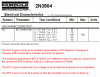
How do you determine what the gain will be for a transistor. I have a PN2222A transistor and the datasheet give lots of different numbers. How can you determine what HFE number to use when designing a circuit?
Hi,
I am surprised that you did not find the minimum gain spec for that
transistor on the data sheet. This is the gain they say will be the
minimum found in any of their transistors.
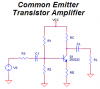
The thing is though, is that a circuit can not usually be designed that
depends highly on the gain of the transistor anyway, as you have to
assume that it changes over temperature too. This means you should
test your circuit and make sure it still works as planned.
For example, a circuit that requires a gain of 50 using a transistor
with a min gain of 50 wont work right, so you design a circuit so
that it only requires a gain less than the min gain spec and set up
the design to force a gain of say 25 to 40. This will allow the
transistor to work at a gain that it should have even with a change
in temperature.
With some transistors they show the change in beta with temperature,
but with most they dont. It starts out low with lower temps, then
goes up to some peak, then dips low again for very high temps.