flatfootskier
Member
Hi,
I'm looking to provide an input to a microcontroller which allows it to know when my Economy 7 (cheap rate UK night time electricity with dual meters & a powerCo owned switch) is enabled.
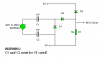
So I need to safely provide either a closed circuit or a 5v output. I'm thinking along the lines of an opto isolator, but don't know how best to drive that from 230V (250V in reality for me).
Main requirements are:
1. Safe
2. Minimal power consumption - it'll run 24*7*365
3. Reasonably inexpensive, but not at the expense of safety, at all.
I'm pretty appreciative of most of the risks of working at different voltages, reasonably competent at electronics, but totally unfamiliar with conmponent design at line voltages. The suck-it-and-see approach I would use at 5v seems innapropriate for this and I felt it better to collate the experience of the wider community.
Thanks in advance.
I'm looking to provide an input to a microcontroller which allows it to know when my Economy 7 (cheap rate UK night time electricity with dual meters & a powerCo owned switch) is enabled.
So I need to safely provide either a closed circuit or a 5v output. I'm thinking along the lines of an opto isolator, but don't know how best to drive that from 230V (250V in reality for me).
Main requirements are:
1. Safe
2. Minimal power consumption - it'll run 24*7*365
3. Reasonably inexpensive, but not at the expense of safety, at all.
I'm pretty appreciative of most of the risks of working at different voltages, reasonably competent at electronics, but totally unfamiliar with conmponent design at line voltages. The suck-it-and-see approach I would use at 5v seems innapropriate for this and I felt it better to collate the experience of the wider community.
Thanks in advance.

") ..!!
..!!