Hi, I need help to design a circuit
I'm buliding a scuba torch and need a small circuit to switch my ligth on and off.
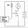
I'm going to use a halleffect relay as switch and use a magnet to activate it.Then i need some kind of relay that can handle currents above 10A.
I've seen a small circuit with a power mosfet to act as relay and want to build something similar.
My knowlegde in electronics is very basic.
Torch spec:
Battery: 12V 9Ah
Bulb: 50W or 100W
Any help would be appreciated.
I'm buliding a scuba torch and need a small circuit to switch my ligth on and off.
I'm going to use a halleffect relay as switch and use a magnet to activate it.Then i need some kind of relay that can handle currents above 10A.
I've seen a small circuit with a power mosfet to act as relay and want to build something similar.
My knowlegde in electronics is very basic.
Torch spec:
Battery: 12V 9Ah
Bulb: 50W or 100W
Any help would be appreciated.
")