Right, this is a tricky one, so im gonna ask for the help of experts like you guys...
I need to design and build a variable power supply. Sounds easy? heres the specs...
Suppy voltage is from a 3V lithium battery.
Required output voltages is: 2.0VDC --> 14VDC @ 1mA continous, in 0.25V steps (48 steps)
The output must be able to turn on and off. (via a transistor i guess).
OK, so now your thinking "easy, use a charge/pump regulator and a variable resistor"... Well yes that would work, but it also needs to be controllable by a microprocessor, so the micro can change the voltage.
--
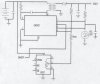
So i looked at the LM2623 device, looks ok to me, will do the job, but cannot be controlled by a processor without a digital pot?
Any ideas welcome. Needs to be really super cheep and easy to setup/calibrate.
Joe
I need to design and build a variable power supply. Sounds easy? heres the specs...
Suppy voltage is from a 3V lithium battery.
Required output voltages is: 2.0VDC --> 14VDC @ 1mA continous, in 0.25V steps (48 steps)
The output must be able to turn on and off. (via a transistor i guess).
OK, so now your thinking "easy, use a charge/pump regulator and a variable resistor"... Well yes that would work, but it also needs to be controllable by a microprocessor, so the micro can change the voltage.
--
So i looked at the LM2623 device, looks ok to me, will do the job, but cannot be controlled by a processor without a digital pot?
Any ideas welcome. Needs to be really super cheep and easy to setup/calibrate.
Joe