Continue to Site

Welcome to our site!

Electro Tech is an online community (with over 170,000 members) who enjoy talking about and building electronic circuits, projects and gadgets. To participate you need to register. Registration is free. Click here to register now.

  • Welcome to our site! Electro Tech is an online community (with over 170,000 members) who enjoy talking about and building electronic circuits, projects and gadgets. To participate you need to register. Registration is free. Click here to register now.

Designing a Two stage CE-CE BJT amplifier

Status
Not open for further replies.

Rev*

New Member
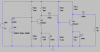
Hello, I would like to design a two stage ce-ce amplifier so that my output power at the second stage is somewhere around 150-200 mW at the load of 50 Ohms.
Given that
Vcc=12v
Q1: BSX20
Q2: 2N4427
I am a beginner when it comes to build amplifiers, I've attached my attempt of designing such amplifier, would appreciate some help in order to correct and improve my design thanks.
 

Attachments

  • amp.png
    amp.png
    42.3 KB · Views: 239
What frequency range are you designing for?

JimB
 
It is illegal in most countries to transmit that much power at radio station frequencies without a licence. Enclose your circuit in a earthed and grounded metal case and the room and test equipment in an earthed and grounded Faraday cage.

The largest electronic parts distributor in North America (Digikey) does not know and does not have an antique BSX20 transistor. The 2N4427 is also obsolete.
The RB base biasing resistor values are much too high.
The coupling capacitor values are also much too high for VHF frequencies.

Thanks for the feedback Audioguru, I am aware of the regulations with that I want to add that this is merely for learning purposes. Given these two transistors I would like to know what combination of resistors and capacitors I must have to try and achieve such power theoretically and what are the factors I must consider.
 
Why use antique transistors that are not made anymore?
Did you learn about transistor hFE range and how to bias a transistor? Did you learn about radio circuits?
Sorry, I am not a teacher.
 
Thanks for the feedback Audioguru, I am aware of the regulations with that I want to add that this is merely for learning purposes. Given these two transistors I would like to know what combination of resistors and capacitors I must have to try and achieve such power theoretically and what are the factors I must consider.

Supposed 'learning purposes' doesn't give you the right to break laws - I only robbed the bank for 'learning purposes', not really an acceptable excuse.
 
Status
Not open for further replies.

Latest threads

New Articles From Microcontroller Tips

Back
Top