Continue to Site

Welcome to our site!

Electro Tech is an online community (with over 170,000 members) who enjoy talking about and building electronic circuits, projects and gadgets. To participate you need to register. Registration is free. Click here to register now.

  • Welcome to our site! Electro Tech is an online community (with over 170,000 members) who enjoy talking about and building electronic circuits, projects and gadgets. To participate you need to register. Registration is free. Click here to register now.

design questions

Status
Not open for further replies.

redpowersmoker

New Member
Hi guys new here like to say hello....

i gotta question and just wanting to make sure that this will work properly or if not you could point me in the direction i need to go

im using 24v ac to switch a 12v relay for something in for irrigation system this is what i was figuring out

there is going to be a 12v input will trun to the positive input on the relay
the ground will also run into the relay and also to the output of the box


now this is where im asking for your opinion

also coming in the box is a 24vac line
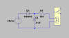
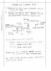
i was gonna run it to a bridge rectifier full wave and then put a 12v zener diode on the positive out and the negative out

run the negative to the 12v ground thats already in the box and then run the 12v positive to the switching terminal on the relay.

if my explaination is to confusing ill make a schematic for you to see in microsoft paint...

thanks for any of your opinions in advance
 
Why not just use a relay with a 24VAC coil, and dispense with everything else?
 
Ya use a 24VAC relay thay are common.
You would need a filter cap and a current limit resistor with one zener to make 12VDC from your 24VAC.
What are your extra zeners for?
What is +12 Rem?
 
what it is i am putting 12v low voltage lights throughout my yard but i want certain ones to turn on with my irrigation system

the 12v in is coming from my transformer and the 24vac is the output from my irrigation controler

the 12v remote is just a wire that i am going to use so that if i decide to turn on all my lights at once i can without having to turn on my irrigation system... the only thing im using the 24vac is to just trigger the relay for the lights... my irrigation controller dosent have the umph to supply several 12v lights...

and the zenor diodes are for stopping backfeeding and also as a voltage regulator..
 
Last edited:
OK use a 24VAC relay and a SPDT switch. Wire one side of the switch using power from the controler and the other side hooked up to the 24VAC power so you can turn the lights on any time you what.
 
You should not have any connection between the coil side of the relay and the load side. As long as it is a standard relay, you just power the coil with 12 V and it operates. The contacts are just like a switch.

You can just measure the resistance of the coil, and buy a similar value resistor which you put in series. That would be just about the same value as you would need with a zener diode.

The connections on the relay (GND, trigger, +in and +out) make me think that it isn't a standard relay. Can you post more details?
 
its just a standard automotive relay...

theres another pin on the relay but its not used..
im just wanting to use the 24vac and convert it to 12vdc only to trigger the relay not run it..the 12v load in is what will run it and the 12v out is what will power the lights. the zener diodes i just figured as a voltage regulator and to stop the voltage from backfeeding voltage...
 
Would this work for you?

Home run each of the light zones to a control box.
The control box would consist of a 24 VAC coil relay for each of the 12 V light zones.

An center off switch would be used for each zone. Their positions would read (lights controlled by sprinker) (off) and (lights on).
 
The standard 12VDC automotive relays are not very good for this application. Their coil resistance is like 65 to 85 Ohms, so it takes a lot of power to operate them. P = E^2/R = 12^2/85 = 1.7W. I have some smaller 12VDC relays that have a coil resistance of 400 Ohms, so the power is only 0.36W. Lots of these available surplus at AllElectronics. At that level, you can just run them off your irrigation controller by using just one diode, one resistor and one capacitor, like this:


Your approach of trigger from 24Vac, power from 12Vdc has a serious flaw. Once triggered, what resets it?
 

Attachments

  • rly.png
    rly.png
    7.8 KB · Views: 118
Last edited:
We could modify my suggested design to include a single switch for "all on". by adding low current triacs or optomos relays, one for each zone.
 
the 24vac is the output from the irrigation controller it will be at a constant power while that zone of the irrigation system is on... so the 24vac is what will hold the relay closed for power to flow through..
 
im just trying to figure this out im fairly new with diy electronics so you will have to excuse me if im not "up and up" on everything...
 
Per a request by PM, I've uploaded a schematic which can easily be expanded to 4 zones.

It does mean that the control of the lights are at a central panel and that home runs are run to each lamp zone. A "home run" means a single cable.

There may be a zone which does not have a corresponding sprinkler and that's OK too.

If it were me, I'd like a switch at the entrance of the home which would turn on all the lights. That could be done using X-10 technology and say a 4PDT relay.

While multiple 4PDT relays could be used, they could easily be replaced with a solid state equlivelent. So, in esscence multiple 4PDT relays or solid state replacement could expand the number of zones by a multiple of 4.

This does not address cost. Bosch 12 V 30 Amp relays are inexpensive. It's possible that high current DC rated contact relay with a 24 VAC coil is expensive.

So, again a choice could be made to use the inexpensive relays and detect the presence of the 24 VAC optoelectrically and activate a 12 VDC coil.

This could easily be accomplished using the DIN rail and the enclosure system with the 1/8" aluminum plate in the bottom. The construction technique is expensive, but it's easy to troubleshoot.

The major concern is picking a relay with a 24 VAC coil which can switch DC at or above the needed current. Power = VI. You know the wattage of the lamps, the number of the lamps and V=12, so you can figure the current I or contact rating needed for each zone. Surplus relays are a good place to start.

The switches could be a mineature toggle switch or the industrial type switches with switchblocks (very expensive).

Two AC rated breakers would complement the system. One for the light power and one for the sprinker power.

Not knowing the number of zones and the current drawn for each zone, makes it tough to design something.

Later, one could change the "all lights on" switch to say "Lights: (on, auto, remote). Remote would be through an X-10 module, auto: controlled by sprinker and ON. I haven't thought this function through yet. "auto" is "controlled by sprinkler"

I'll be happy to answer any questions.
 

Attachments

  • Sprinkler lights 001.jpg
    Sprinkler lights 001.jpg
    63.7 KB · Views: 154
ok since im learning all this slowly what all exactly is wrong with my design... and ive tried googling a relay that runs 12vdc but operates witha 24vac coil to operate the relay... anybody got any hints on to where to find one?
 
ok since im learning all this slowly what all exactly is wrong with my design... and ive tried googling a relay that runs 12vdc but operates witha 24vac coil to operate the relay... anybody got any hints on to where to find one?

Are you asking for about the relay contact rating? If so, the coil rating is one thing; the contact rating is another, and the two are somewhat independent of each other. Typical small relays have a contact rating something like 5A 120VAC/2A 28VDC, while the coil could be 5, 6, 12, 24 or 48Vdc, or 24, 120Vac.

Look at the page of relays at Alelectronics I linked to several posts back. It has a variety of relays with different coil voltages and different contact ratings.

A relay with contacts rated for 28Vdc 2A could be used to switch anything from 1V to 28Vdc provided that the current is less than 2A.
 
Status
Not open for further replies.

Latest threads

New Articles From Microcontroller Tips

Back
Top