Hello all ,
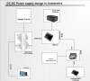
I wish to design a switch mode power supply , dc-dc buck-boost converter, ('with Vin - from 12V to 48V ) and Vout from 2V to 20V with Iout - upto 6A, There are many IC's available from Ltspice and Texas Instruments. I have design the block diagram , but I am not sure what should be done at the output of the ECU, where the KL31 is neg for the ECU
The ECU (electronic control unit)
kl30 and kL 31, with pos and neg of the ECu
The output of the SMPS IC will be feed through the KL30 through the ECU , and then through KL 31 to the loads connected to the ECU .
In some cases there are multiple ECU's connected to ECU's.
A inverting power supply from kl31 should it be connected ? I am confused about the negative currents from the ECU back to the main power supply.

Regards
I wish to design a switch mode power supply , dc-dc buck-boost converter, ('with Vin - from 12V to 48V ) and Vout from 2V to 20V with Iout - upto 6A, There are many IC's available from Ltspice and Texas Instruments. I have design the block diagram , but I am not sure what should be done at the output of the ECU, where the KL31 is neg for the ECU
The ECU (electronic control unit)
kl30 and kL 31, with pos and neg of the ECu
The output of the SMPS IC will be feed through the KL30 through the ECU , and then through KL 31 to the loads connected to the ECU .
In some cases there are multiple ECU's connected to ECU's.
A inverting power supply from kl31 should it be connected ? I am confused about the negative currents from the ECU back to the main power supply.
Regards
")
