Continue to Site

Welcome to our site!

Electro Tech is an online community (with over 170,000 members) who enjoy talking about and building electronic circuits, projects and gadgets. To participate you need to register. Registration is free. Click here to register now.

  • Welcome to our site! Electro Tech is an online community (with over 170,000 members) who enjoy talking about and building electronic circuits, projects and gadgets. To participate you need to register. Registration is free. Click here to register now.

Design Frequency to Voltage Circuit of LM2907N

Status
Not open for further replies.

swear_swear

New Member
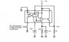
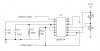
I have followed the datasheet of LM2907N to design a frequency to voltage circuit. But I still cannot be sucessful to make a larger voltage output range. It only can be varying within 0-3V output for 40Hz input.
Can any professional give me a design which can achive a higher range of output, e.g: 0-50Hz to have an output range 0-12V. That range can give me a larger range to have a more accuracy signal to do speed control.
Also, the ripple of the output will affect the output range or not?
Thank you very much.

:roll: :roll: :roll: :roll: :roll: :roll:
 
Sorry, can you give me any advice of which type can do such thing?
Or any other methods can achieve the task?
Really need help.
Thank you a lot.
 
Why not connect the output to a transistor (base). You can then drive the transistor to give you an output of up to Vcc.
Klaus
 
Stick with the LM2907

I'm sure the LM2907 is capable of doing what you want,
it just needs some component changes to set the range.

The IC has three basic sections, a trip amp, a charge pump and an op amp,
if the charge pump (and following integrator) can't be set to the desired time constant then the op amp can give lots of gain.

As you don't mention any component values other than imply you are following some datasheet,
Try C1 (from pin 2 to ground) as 2uF
and R1 (from pin 3 to ground) as 10k

or
C1 = 1uF
R1 = 20k

with everything else as per the datasheet (I'm looking at https://www.electro-tech-online.com/custompdfs/2003/07/LM2907.pdf )
Should give 50Hz as 12v out with a 12v supply ... BUT
As the circuit will lose some voltage it will stop short of 12v out.

To do better requires more info - supply voltage, rest of circuit components ?
 
Thank you for your reply.
As I want to know the attached circuit is correct as what you mention?
But i want to know the accuracy of this circuit?
because i use it to deteminate of the speed of the motor and by using this DC voltage to do control. So, can you give me any advice about the accuracy of the circuit?
Thank you very much~
:idea: :idea: :idea: :idea:
 

Attachments

  • LM2907.JPG
    LM2907.JPG
    16.1 KB · Views: 2,436
Sorry, can anybody give me advice or the circuit is correct or any incorrect place?
Thank you very much~
:!: :!: :!: :!:
 
LM2907 - 8 pin package

As you show the 8 pin package circuit,
I assume this is what you have - there is a 14 pin version as well.

The 8 pin package has the op-amp input stage's inverting input connected to ground (via pin 8), the non-inverting input is on pin 1.
This op-amp works as a sort of 'trip amp', whenever the input on pin 1 exceeds the voltage on pin 8 (0v), the output to the charge pump will go high, being low at all other times.

This is important as the input signal MUST cross this zero volt threshold :!:
The input signal must therefore go positive AND negative for the circuit to work.

Other than that (you said the circuit worked, just gave the wrong range), the diagram you posted is correct, the vaues should be OK.
 
Thank for reply.
I have made the circuit but seem not work.
I don't know why. But I have used the 14 PINS version (LM2907N).
I am before use the below circuit and it work.
So, what can I do.
Please help~
:?: :?: :?: :?:
 

Attachments

  • LM2907_810.jpg
    LM2907_810.jpg
    23.5 KB · Views: 1,982
change of voltage range

Hi.
I'm trying to sense the freq of a square wave from 10KHz - 40KHz range. Now I understand the chip gives you a 0volts to Vcc variation for 0 Hz to fmax.
But I need 10khz to 40khz give me a 0 volt - Vcc variation. Any suggestions on how to implement that?
Also, I need to be very conservative wrt adding components. Adding 2 more ics to do the trick is not an option.
Don't worry about calculating the R1,C1,C2 values. just need a hint on how to make this change.
Thanks in advance.

( i know i;m too optimistic to expect reply on a 8yr old thread)
 
Last edited:
Status
Not open for further replies.

Latest threads

New Articles From Microcontroller Tips

Back
Top