Continue to Site

Welcome to our site!

Electro Tech is an online community (with over 170,000 members) who enjoy talking about and building electronic circuits, projects and gadgets. To participate you need to register. Registration is free. Click here to register now.

  • Welcome to our site! Electro Tech is an online community (with over 170,000 members) who enjoy talking about and building electronic circuits, projects and gadgets. To participate you need to register. Registration is free. Click here to register now.

Dell 2407WFPb dies and revives when he wants.

Status
Not open for further replies.

k4wers

New Member
Hi from Argentina, this is my first post.
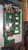
A friend had a Dell 2407WFPb laying on the floor of his apartment and i volunteered to repair it.
The monitor works fine but it doesn't even turn on other times.
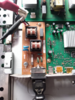
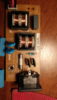
Opened it and this was the discovery, a black transistor without markings, that looks burnt.
A leak-like stain in the PCB board around every transistor.

My first idea was to cook it like a GPU revival method but since this has PVC cables attached didn't took that route yet.

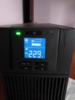
I recently added an "APC power bank and stabilizer" to my rig, because I had crash problems with mi 1080ti, after the purchase realized that I have not 220 as the electric company said, I have 189/209...
The APC was the solution for my PC, now it runs smooth.
Maybe the APC will "fix" the monitor problem as my friend does not have such a stabilizer, sure that he has less than what the monitors needs to run, but looking at those pictures I want to ask your opinion before trying to put it back together.

Thanks.


. 6fd8888b-9211-4e07-a673-f3226dd30288.png6563b683-5193-464d-bd30-89ced8d61d15.pngd4dd1a64-96a3-4f63-91ca-5da3e0fea56e.pnge1a7bf7f-6aa6-4111-9d77-6a495b72560b.pngf9afa13c-da58-4a22-80de-64b902bd8a42.pngvid1.pngvid2.pngvid3.png46a3e8ec-5695-4bc0-8662-c8d8752d84ae.png0739a3b7-5b8f-4bf3-9f5f-e7436ea34b44.png
 
My first thought would be failing electrolytic caps in the power supply section.

The marks on the PCB appear to be small areas of varnish type material, something like a selective conformal coating over something they consider sensitive rather than dipping the whole board and protecting areas that must stay clear.
 
I'd highly recommend one of these little component testers, they are very cheap on ebay.
They will identify transistor pinouts and give the generic type (PNP / NPN) and gain etc., give resistor values - and give capacitor values plus the capacitor internal resistance (ESR).

Someone else on here recommended them and I have found it to be extremely useful. They are sold as just the circuit board module or with various case / case kit options. The "flat pack" acrylic case may look like cardboard in ebay photos, as the parts have protective paper on both sides.

Examples:


Mine:

ComponentTester_600.jpg
 
Thanks RJENKINGB And NIGEL.
It looks like the eBay thing is for loose components, these are all attached to the board and I'm not in a mood for full disassembly, but I'll consider it for future projects. :)
Right now this is what I have....

1. A decent and stable power input. 230v.
2. A ¿Working? power supply giving around 250 in direct, and 185 in alternate.
3. A resistor that does not BEEP when Continuity test. (the light blue big one)
4. A burnt smell in the PSU area when pugged up.

¿Next step? ¿Change the resistance?

The big capacitor from the original post looks good, it charges and discharges when unplugged, and also has not continuity beep.
One thing that I realized is that the first radiator-mosfet hast not a thermal pad and only one of the "yellow wrapped boxy things" from the original post has a tiny thermal pad, plus the shield has a black stain like there is hot air flowing through it.
 

Attachments

  • 57e0607f-80c1-40f4-b494-c93ffb248bd8.png
    57e0607f-80c1-40f4-b494-c93ffb248bd8.png
    448.5 KB · Views: 242
  • fba5998f-2397-44d7-9d41-cc1370da4eca.png
    fba5998f-2397-44d7-9d41-cc1370da4eca.png
    1.5 MB · Views: 224
  • 97dc8ceb-85d6-468b-99b6-f5cd6507ee12.jpg
    97dc8ceb-85d6-468b-99b6-f5cd6507ee12.jpg
    113.2 KB · Views: 224
  • c3ead51c-7186-4d79-932e-99a74d47fdaa.png
    c3ead51c-7186-4d79-932e-99a74d47fdaa.png
    1.7 MB · Views: 220
  • c07031ff-38d0-4d4f-8088-102c146b4d35.png
    c07031ff-38d0-4d4f-8088-102c146b4d35.png
    1.3 MB · Views: 219
There it is the schematic for the power supply.
 

Attachments

  • 207782153-Dell-2407-WFP-Power-Supply-Rev-A11-Schematic-Diagram.pdf
    182.1 KB · Views: 226
The first page is the PFC (Power Factor Correction), and supplies +B to the power supply itself on page 2. The main power supply just seems to provide 19V via fuse F701.

The problem is likely to be that almost all the power supply is live to the mains, making it 'difficult' and 'dangerous' to measure voltages.

There are a couple of trip circuits, IC603 and Q602/Q603.
 
Thanks you all... I've "Fixed" it.
I put that board on the oven 10minutes 190 Degrees C.
The capacitors went bulge and some 6 started leaking xD but the thing works now.
:) Thanks, and ill keep you updated.
 

Attachments

  • e1a7bf7f-6aa6-4111-9d77-6a495b72560b.png
    e1a7bf7f-6aa6-4111-9d77-6a495b72560b.png
    1.1 MB · Views: 220
Testing for "random" shutdown or caps blown up.
 

Attachments

  • 854abf72-0f43-4ed9-91b2-0f8c879d3723.jpg
    854abf72-0f43-4ed9-91b2-0f8c879d3723.jpg
    58.4 KB · Views: 219
Status
Not open for further replies.

Latest threads

New Articles From Microcontroller Tips

Back
Top