Continue to Site

Welcome to our site!

Electro Tech is an online community (with over 170,000 members) who enjoy talking about and building electronic circuits, projects and gadgets. To participate you need to register. Registration is free. Click here to register now.

  • Welcome to our site! Electro Tech is an online community (with over 170,000 members) who enjoy talking about and building electronic circuits, projects and gadgets. To participate you need to register. Registration is free. Click here to register now.

Delayed start for 555 using reset pin

Status
Not open for further replies.

darryl_co

New Member
Hi,
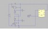
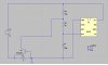
I am trying to use the Reset Pin of NE555 to give it a switch off and delayed start but failed as the 555 requires just above 0.7v on the reset pin to become on again.I had connected pin 4 to plus via a resistor and capacitor at pin 4 to ground.I need to create a short circuit protection for my circuit using 555 to drive an inductive load through a transistor.When current exceeds 0.6A across the R1 or R3 the transistor Q1 or Q2 conducts and brings Point A or B to Vcc or ground.I need instant shutdown off 555 and a delayed start back.I have a spare opamp that can be used if needed.Either of The circuit consisting of R1,R2,R5 and Q1 or R3,R4,R6 and Q2 can be used.
 

Attachments

  • Delay start.asc
    1.8 KB · Views: 142
  • Delay Start.JPG
    Delay Start.JPG
    53.1 KB · Views: 269
How much delay do you need? mS? Secs? Mins?.....
Something based on this (the graph shows the Reset pin voltage)?
DelayedTrigger.gif
 
Last edited:
I need a delay of 2 seconds.On excess current drawn instant switch off (IC resetted) and reset for 2 secs.See my orig schematic
 

Attachments

  • Delay start_orig.asc
    1.3 KB · Views: 159
  • Delay Start_orig.JPG
    Delay Start_orig.JPG
    48.2 KB · Views: 212
Here's how I'd do it, using a couple of CD4093 gates coupled as a monostable. (You need CD4000.lib to run the sim).
 

Attachments

  • ResetHold2.asc
    2.2 KB · Views: 155
Last edited:
When power is switch on I get the power on delay(2sec) but when the current exceeds and transistor q2 switches the delay is gone.Please help
 

Attachments

  • Delay start_orig_mod.asc
    2 KB · Views: 131
Your sim has R4 connected to ground, so Q2 stays off and there is nothing to reset the 555 after the initial power-up reset. Did you try the sim I posted?

Here's a revision of your circuit, with overcurrent simulated by turning on Q2 with V2 :
 

Attachments

  • Delay start_alec.asc
    2.3 KB · Views: 147
Last edited:
"Did you try the sim I posted?" Yes I did try but for that I would have to add another IC in my board.I had already designed my board thinking that the 555 would reset below 1/2 Vcc so a standard RC delay would do the work.My only help is using the spare opamp.What is V2? My only sensing is the voltage drop across R3 that would develop 0.6V on excess current drawn and switch on Q2.I can add a transistor like Q2 in the + line to bias the Q2 if that can solve the problem
 
What is V2?
It's merely a Spice voltage source. You have nothing in your 'delay start orig.asc' circuit to raise the current through R3 to turn on Q2; so to get the effect of increasing the voltage drop across R3 I added V2 instead to turn on Q2. It's for simulation only, to test the delayed start of the 555; your real circuit won't need it.
 
This Circuit Works.
 

Attachments

  • 555-Delayed-Power-ON.PNG
    555-Delayed-Power-ON.PNG
    7.7 KB · Views: 306
Here's another modification, with hysteresis added to make the opamp snap-action. V2 is positioned differently but again simulates the voltage drop change across R3.

Edit: This asc file is wrong. Ignore it. See later post
 

Attachments

  • Delay start_alec2.asc
    2.4 KB · Views: 164
Last edited:
I thought you already had it? You have a LM358 in your schematic :).
 

Attachments

  • lm358.zip
    16 KB · Views: 156
I just placed an opamp and named it lm358 to show the spare opamp available.In a pnp transistor shouldnt the emitter be higher than the base and be connected to the plus and the base be connected after the 1E resistor? Can we connect the collector emitter of of a transistor directly across a capacitor to discharge it? wouldnt the discharge current be high enough to damage the transistor?
 
Last edited:
In a pnp transistor shouldnt the emitter be higher than the base and be connected to the plus and the base be connected after the 1E resistor?
Good catch. My bad. Revised asc file attached.
Can we connect the collector emitter of of a transistor directly across a capacitor to discharge it? wouldnt the discharge current be high enough to damage the transistor?
It's perfectly ok for low values of capacitance, where the total energy involved is insufficient to cause significant heating.
 

Attachments

  • Delay start_alec3.asc
    2.4 KB · Views: 155
Last edited:
Status
Not open for further replies.

Latest threads

Back
Top