Thanks, here is the background on the above circuit....(below the starred line below)
Sorry to have bothered you with this.......this circuit is being offered as a donation to those who have an interest in using it......which means.....anybody who uses synchronous rectifier fets with bridges/forwards.
To be honest, if you are not interested in the useage of this circuit, then i have to confess, it would not be worth your while to "reduce" it, and i would not like you to waste your time with it.....the circuit is a donation to anybody who wants to use it.....they, of their own volition, may then wish to reduce it......whether of course they wish to post any reduction here is up to them....
___************************************************************************___
____--___---____--___________
-____
The question encompass's one of the last "great untruths" of the SMPS world.
That is, that there is in fact no satisfactory way of avoiding reversal of current in synchronous Bridge/Forward converters when they go into light load.
Most synch rect FET driver App Notes and datasheets will tell you that there is...but its a lie.!
The reversal of this inductive current , is often followed by a switching off of the synch FET, and resultant overvoltage spike, (due to broken inductive current) and large losses in TVS's / snubbers etc. (as shown in sim attached in LTspice)
...So there are no ways round this.....well that is, other than disabling the synchronous FETs when the converter goes into light load.
The other way is to have a controller which always switches, so that the current reversal in light load is always limited........and at no_load the output inductor current just shuttles back and forth, with an average of zero Amps....however, there are no offtheshelf controllers which do this with sych FETs.....you'd have to make your own out of a micro
All offtheshelf synch FET drivers try and sense the reversing current, and then turn off the synch FET after its been sensed...but this is too late...because its already happened by then.
Also, the sense resistors used are very low value, and the signal from them is so small it gets drowned out by noise......so one ends up settling for more reversed current than one would like.
_______________-----_____________
So..... i find the standard offtheshelf sync rect drivers leave one open to overvoltage spikes due to the SMPS going into light load suddenly......and then the output inductor current reversing and going the "wrong way" back through the sync rect FET....then the sync rect FET turns off...and the output inductor current has been suddenly broken (and now has nowhere to go)....and thus an overvoltage spike results.....the attached LTspice simulation shows the situation happening at the 2ms point.
(if you change it and make the 1e20R resistors equal to 0.1R (or less), then the effect is mitigated.)
https://www.edaboard.com/threads/sy...ong-too-high-reverse-inductor-current.388033/
The extra “mitigation circuitry” is not usually tolerated by most project managers….because they say that the offtheshelf solutions must work…otherwise they wouldnt be on the market……but the offtheshelf ones only detect current reversing through the sync rect fet after its started happening…..which is too late really. The offtheshelfer’s also usually detect current reversing through the sync rect fet by “Looking” at the voltage across the rds(on) of the sync rect fet……and AYK this is not a fixed voltage because of rds(on) variation with temperature.
So really, chunky TVS's end up being needed across sync rect fets......or even RCD Clamps.
Most offtheshelf sync rect fet controllers are pretty dreadful things…..and many of them (their datasheets) are honest enough to say how bad the situation of detecting reverse current through the sync rect is…and offer you a way to mitigate noise here by putting in your own compensatory "stray" inductor, to mitigate the effect of stray inductance of eg the TO220 legs, etc.
Here is the NCP4303 sync rect controller
https://www.onsemi.com/pdf/datasheet/ncp4303-d.pdf
.....it shows the "compensatory inductor" that is needed.
It obviosuly has to be "tuned" in value to your PCB layout "strays" etc.
_____----_____
Also, the Current doubler rectifier, with its two output inductors, and single txformer secondary, is the best topology by far for sync rects, because even if the sync rect fet turns off whilst conducting reverse current, there is still some path for the output inductor current to go.
___---____
Truly , you should not be running synch FETs (with forwards or bridges) unless you either ..
1....keep switching down to no_load so your inductor current just harmlessly oscillates back and forth when in no_load or light_load
2.....disable your synch rects in light load
(which is what the "donation" circuit of the top post does)
3....Literally put a schottky in series with the output inductor, so its current cannot reverse.
...if you do not do either of these things...then you are operating a dodgy SMPS...but you may be getting away with it, because your SMPS is usually loaded above the level where this problem happens (ie just above that point where the output inductor current goes discontinuous) .....or it spends a lot of time in no_load, or very light load, where the controller will then actually disable the synch rects by itself.
__________
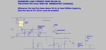
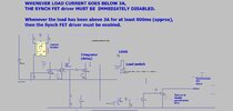
Attached please find the circuit needed with all bridge/forward synchronous FET controllers/drivers.
No Sync FET Controller App Note will ever tell you about this....
Very many power supplies always operate at or above 30% load virtually all the time, so they never see the "reverse current nightmare" of synchronous FETs anyway.......so the vendors just hope you're in that bracket....
But really , you need the attached circuit (LTspice and jpeg attached)
It simply shuts off the synch FET driver when the load goes below 30% of max.
It shuts it off straight away....but waits a second or so before enabling the synch FETs when the load goes above 30%
As discussed, the only other way round this, is to use the stray inductance discussed in the NCP4306/3 datasheets.......but good luck to you if you start tiddling about with that....it will take you ages to tune and it wont be tuned for all cases of transient etc....and when you change the FETs , the added stray inductance will need to be changed again.......basically, your company will need to ship you with the product, so you are there to tiddle the added stray inductance about so as to keep fixing it.
.....Its noteable that this "added stray inductor fix" for synch FET controllers was never seen until many years of sales of synch FET controllers...then the failure rate was so high that the semico industries had to 'fess up about it.........millions of tons of scrap power supplies laying waste due to the "forced silence" over this problem.
...Of course , there is another way to fix the rev current nightmare of synch FET controllers...and that's to add enormous snubber/clamp network.....but that isnt the way to go here.
What you mustn't do, is be like most engineers, and just pretend the problem doesnt happen....and rely on the fact that above 30% loading , your safe anyway.....and in the other regions, the FETs will last out a bit of time before they go pop....and then you can just put it down to a "weak batch of FETs".
So anyway..please find the synch FET delayed_enabler/disabler circuit as attached..(its in the top post).....any suggestions for reducing the component count much appreciated?
______
Please respond if you want the sims referred to above, and i will donate them to you.