Continue to Site

Welcome to our site!

Electro Tech is an online community (with over 170,000 members) who enjoy talking about and building electronic circuits, projects and gadgets. To participate you need to register. Registration is free. Click here to register now.

  • Welcome to our site! Electro Tech is an online community (with over 170,000 members) who enjoy talking about and building electronic circuits, projects and gadgets. To participate you need to register. Registration is free. Click here to register now.

Define what kind of osilator is?

Status
Not open for further replies.
What is the value of C1? is it 1.5nF (1500pF)? I doubt that it is 152 Farads.:D
You need to be consistent with your units.
 
A cheapo Chinese 1.5nF capacitor is marked 152 (1500 pF). The "2" says how many zeros.
Europeans mark it as 1n5.
Americans mark it as 0.0015uF.
 
Last edited:
actually, sometime between 1980 and now, most manufacturers have gone to the digit-digit-multiplier method of marking caps and resistors.... including american manufacturers.... and even if it's not printed that way on the device, it's used in the part number when you order them. marking them on a schematic that way, is something else entirely. when you scan a schematic, and don't have quite enough resolution to tell the difference between a 2 and a 7, or a 6,8,9 or 0, or a 4 and a 1, then the 3 digit code becomes useless, and you're better off marking it in the traditional manner.
 
Back to basics: The transistor has no source of base current, so the circuit shouldn't oscillate. Arvinfx, are you sure there is no resistor anywhere in the circuit? If not, perhaps it is in the transducer. Did you buy this, or remove it from some other product? Can you give us a part number?
 
Back to basics: The transistor has no source of base current, so the circuit shouldn't oscillate. Arvinfx, are you sure there is no resistor anywhere in the circuit? If not, perhaps it is in the transducer. Did you buy this, or remove it from some other product? Can you give us a part number?

Ron, read aRVINFX's replies to all the questions I put to him...
 
I have a simulation that works. I'll post results after I have time to refine it a little.
 
Last edited:
I need to see how the base of the transistor can feed the piezo transducer with 45W!
 
as can be seen from this, it takes the kick of turning on the power to get it to oscillate. once it is oscillating, the current through the piezo is 1200mAp-p, and the peak voltage across the crystal is close to 120Vp-p, but there's a 90 degree phase shift between the voltage and current, so the average power the crystal is driven with is probably around 45W. the path for the crystal current is through the 6.8nf cap, not the transistor
 
Last edited:
Your oscillator appears to be squegging at a 500Hz audible frequency. Won't the bursts of mist or the inductors contracting and expanding be noisy?
 
Here are the results of my simulation. If anyone wants to run it, I'll zip all the required files and post it.
 
I need to see how the base of the transistor can feed the piezo transducer with 45W!

Pick of amp on piezo is 1A and as you can see the maximum current base of the BU406 ,it can do it!.

new-bitmap-image-jpg.67710
 

Attachments

  • New Bitmap Image.jpg
    New Bitmap Image.jpg
    105.9 KB · Views: 398
Here are the results of my simulation. If anyone wants to run it, I'll zip all the required files and post it.

This is that what I want! please share it:D
And what is the simulator program's name?
 
Last edited:
LTSpice. you can download it from www.linear.com. AG, the reason the sim is "squegging" is the oscillator would not start on it's own, the power had to be pulsed to get it to start. i had forgotten about using a PWL source, and used a pulse source instead. and if anybody wants to build the simmed circuit, don't use a 3055, as they're only rated at 60V....
 
This is that what I want! please share it:D
And what is the simulator program's name?
Here is a zip of all the files needed (I think) to run the sim.
The piezo actuator subcircuit is called quartz_crystal because piezo crystals have the same circuit topology, just different component values.
The BU406bd is a subcircuit consisting of a BU406 transistor with an ideal 6V zener in parallel with the base, to represent base-emitter breakdown. This zener is modeled as an ideal diode with a forward voltage of 6V, and 10Ω series resistance. I didn't use a "real" zener model because this would add an actual diode in parallel with the base-emitter junction, with its attendant capacitance, etc. Common transistor models do not include base-emitter reverse breakdown.
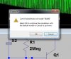
You can descend into the schematics of these two parts by right-clicking on the symbol. This will bring up a dialog box. One of the options is Open Schematic.

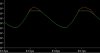
Note that, without the base-emitter breakdown being modeled, the simulation results in a 340kHz sinusoidal oscillation at about 8V p-p.

Note also that breakdown of the base-emitter junction causes beta degradation that is proportional to breakdown current, and is cumulative with time. Here is a thread that contains results of measurements made by one Fred Bartoli that confirms this.

Arvinfx, if you haven't used LTspice, be prepared for a steep learning curve.
 
Thanks Roff.

But when I run the Pspice simulator it gave me two errors one of them is for bu406 and other one is for 1n753.

pspice-jpg.67730


What should I do?
 

Attachments

  • pspice.jpg
    pspice.jpg
    52.9 KB · Views: 358
Thanks Roff.

But when I run the Pspice simulator it gave me two errors one of them is for bu406 and other one is for 1n753.

What should I do?
Here is the 1N753 model.

Code:
.model 1N753 D(IS=1E-11 RS=4.685 N=1.27 TT=5E-8 CJO=3.463E-10 VJ=0.75 M=0.33 BV=6.106 IBV=0.01 )

Copy and paste it into the file standard.dio, which resides in LTC/LTspiceIV/lib/cmp (on my computer).

In my circuit, the BU406 model is already in BU406bd.asc, which gets called by the top level sim, piezo oscillator.asc. Why do you need the model? Are you trying to run the sim with the standard BU406 model? You can do that, but the results will be meaningless, because the model does not include the Veb breakdown.
 
Here is the 1N753 model.

In my circuit, the BU406 model is already in BU406bd.asc, which gets called by the top level sim, piezo oscillator.asc. Why do you need the model? Are you trying to run the sim with the standard BU406 model? You can do that, but the results will be meaningless, because the model does not include the Veb breakdown.

It was great :D

The curve of voltage acrosss B-E of Bu406 on your sim is exactly like mine.

1-5-copy-jpg.67637


I want to make the curve like this :

new-bitmap-image-2-jpg.67863


I think a sine wave could have less EMI and heat losses on switch .
How can I do this?
 

Attachments

  • New Bitmap Image (2).jpg
    New Bitmap Image (2).jpg
    18.8 KB · Views: 308
Status
Not open for further replies.

Latest threads

Back
Top