Continue to Site

Welcome to our site!

Electro Tech is an online community (with over 170,000 members) who enjoy talking about and building electronic circuits, projects and gadgets. To participate you need to register. Registration is free. Click here to register now.

  • Welcome to our site! Electro Tech is an online community (with over 170,000 members) who enjoy talking about and building electronic circuits, projects and gadgets. To participate you need to register. Registration is free. Click here to register now.

Define what kind of osilator is?

Status
Not open for further replies.

arvinfx

Member
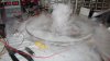
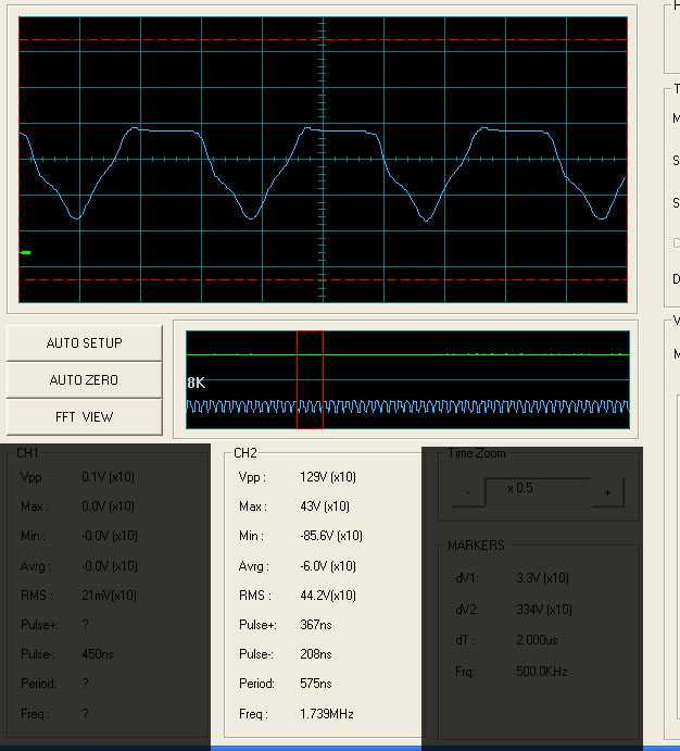
Hi, I built a pizoelecteric foger and it is working well, but when I saw the curve of pizo it is like this:


1-5-copy-jpg.67637


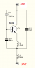
And my circuit is this:

schematic-atomizer-png.67638


Problems:
I don`t know how this circuit works.
What shoud I do to this circuit to reform the slope in sin wave . it seems sin wave but it cut!
I forgot to say, bu406 is realy hot and I need a huge hitsink and a strong fan . I think it related to that curve.
 

Attachments

  • IMG_6141.JPG
    IMG_6141.JPG
    138.4 KB · Views: 238
  • 1-5 copy.jpg
    1-5 copy.jpg
    138.4 KB · Views: 583
  • schematic atomizer.PNG
    schematic atomizer.PNG
    12.1 KB · Views: 508
Please use a Spelling checker:
1) oscillator, not osilator
2) piezo, not pizo
3) electric, not electeric
4) fogger, not foger
5) sine wave, not sin wave
6) heatsink, not hitsink.

Your circuit does not show where the piezo is connected. Is it parallel to C1?
 
How can the transistor get hot? That would imply that it has base bias; and as the schematic shows it has NONE.
 
Last edited:
Please use a Spelling checker:
1) oscillator, not osilator
2) piezo, not pizo
3) electric, not electeric
4) fogger, not foger
5) sine wave, not sin wave
6) heatsink, not hitsink.

Your circuit does not show where the piezo is connected. Is it parallel to C1?

First thank you for correcting me. I really need it.

The piezo is shown in schematic by XT1 between +45V and base of BU406.
 
How can the transistor get hot? That would imply that it has base bias; and as the schematic shows it has NONE.

As you can see the voltage of piezo is 129V and current sink in input is 1A.
it happens for me. I can steam a drop of water when I pour it on Bu406.
 
As you can see the voltage of piezo is 129V and current sink in input is 1A.
Then if the waveform is a sinewave at 129Vp-p then its RMS voltage is 45.6V.
Is the power supply current 1A? Then the total power is 45.6V x 1A= 45.6W and the Mosfet dissipates half which is 22.8W so it needs a pretty big heatsink.
 
How is a Piezo element providing a DC path to the base of the transistor? Do you have a data sheet for it? I have never seen a piezo that doesn't look like a capacitor when measured with an Ohmmeter. Try it.
 
I don't understand how this oscillates. I wonder if it is a negative resistance oscillator, with the negative resistance being provided by collector-emitter avalanche.

The average voltage (-6V) and the flat top on the waveform leads me to suspect that the base-emitter is also breaking down.

I wouldn't be surprised if the transistor has a short, painful life.:D

So, is that fog in the picture from the piezo element, or steam from the hot transistor?:D

EDIT: I just looked at the datasheet of BU406. Vceo is 200V, so that pretty much shoots down my avalanche theory.
 
Last edited:
Then if the waveform is a sinewave at 129Vp-p then its RMS voltage is 45.6V.
Is the power supply current 1A? Then the total power is 45.6V x 1A= 45.6W and the Mosfet dissipates half which is 22.8W so it needs a pretty big heatsink.


Yes the power of my circuit is 45W ,but somenoe else built this circuit from this schematic and the transistor is really cool.!

If we create a sine wave on a transistor in theory we will have 0 loss power on it! but if the wave were square we would have some losses on transistor or switch part of circuit.
 
How is a Piezo element providing a DC path to the base of the transistor? Do you have a data sheet for it? I have never seen a piezo that doesn't look like a capacitor when measured with an Ohmmeter. Try it.

If we contact a piezo to dc voltage it will act az a short circuit for a few mili seconds ( it related to piezo frequency) and after while it goes to open circuit. and in this schematic we will have a ac voltage .
 
I think it's a variant of the Clapp- Oscillator.
Look at Wikipedia, there are some informations about Transistor oscillators.
 
If we contact a piezo to dc voltage it will act az a short circuit for a few mili seconds ( it related to piezo frequency) and after while it goes to open circuit. and in this schematic we will have a ac voltage .

You have just described how a piezo acts as a capacitor; not a resistor.

Did you take the piezo out of the circuit, and measure it with a DC Ohmmeter?
 
The base of a transistor is its input, not its output. Then why is the 45W piezo transducer connected to the base?

When I first saw the schematic of the crystal oscillator I was wondering and asked in my post #2, where is the load (the transducer)?
 
The base of a transistor is its input, not its output. Then why is the 45W piezo transducer connected to the base?

When I first saw the schematic of the crystal oscillator I was wondering and asked in my post #2, where is the load (the transducer)?

I answerd to your question on post #4. I put the transducer exactly on place of XT1.
 
the piezo acts at first as a capacitor, that's what gets the oscillation started. after that it acts as a series resonant circuit, and since there's a 180 degree phase shift at resonance, provides positive feedback to the base of the transistor.
 
the piezo acts at first as a capacitor, that's what gets the oscillation started. after that it acts as a series resonant circuit, and since there's a 180 degree phase shift at resonance, provides positive feedback to the base of the transistor.
Where do you think base current comes from?
 
I have found it is Pierce oscillator.
The circuit you posted is NOT a Pierce Crystal Oscillator because it is missing a few important parts.
Besides, a crystal oscillator has very low power in the crystal. You need a circuit that produces very high power in a piezo transducer.
 
Status
Not open for further replies.

Latest threads

New Articles From Microcontroller Tips

Back
Top