Continue to Site

Welcome to our site!

Electro Tech is an online community (with over 170,000 members) who enjoy talking about and building electronic circuits, projects and gadgets. To participate you need to register. Registration is free. Click here to register now.

  • Welcome to our site! Electro Tech is an online community (with over 170,000 members) who enjoy talking about and building electronic circuits, projects and gadgets. To participate you need to register. Registration is free. Click here to register now.

deconstructed denon hifi for the amp.

Status
Not open for further replies.

RogerJ

New Member
I was given an old Denon HiFi model DC-30 with too many CD/tape transport problems to bother with. I wrecked it for the transformer. But I noticed that the amplifier section of one board could be separated. I felt a 30+30 watt amp project coming on.

After getting the protection circuit relay to close (by shorting p1&2 on PG 052) still no output of audio applied to PG051 P1, 2&3.

Obviously, only someone who knows this unit or has a schematic can help but I thought it worth a try. After a few hours expended getting this far I don't want to be beaten :D

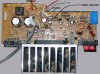
Photo hopefully attached..
 

Attachments

  • DC-30 denon amp board.jpg
    DC-30 denon amp board.jpg
    118.8 KB · Views: 3,592
Check the data sheet for the amplifier module, it may well have a 'mute' pin that needs to be high or low to enable it.
 
Also check that IC052 see what it does. I'm guessing a speaker dethump controller so it probably doesn't matter.

Have you made sure you are supplying the pre-amp voltages +/-15v etc as well as the +/- main amp voltages? Where did PG052 connect to?
 
Externet..thanks for the mute suggestion..I hadn't thought of that. The chip is a SKT4152ii and I've downloaded the pdf.

STK4152II pdf, STK4152II description, STK4152II datasheets, STK4152II view ::: ALLDATASHEET :::

Unfortunately it doesn't give the state of pin6 for the mute to be activated. Ideas? In the datasheet there is a sample appication circuit but I can't figure out what it does - or where it's input comes from.

MrRB..IC052 is a C1237HA proptection device as you supposed. It figured early in my checks as the speaker relay was open. Pin1, PG052 goes to the relay coil which in turn goes to the chip relay driver terminal. Pin2 PG052 has 24v on it so I connected them together. The relay closes so I proceeded on the basis that it's other moniroring functions didn' matter.

On the section of pcb I've snipped of (photo in OP) there may be no preamp...I've assuming sort of line level and using the headphone output of an mp3 player as a source.

The only other active components on the board are Q051 (C1470 then S .SM) and Q052 & Q053 (C124 then ESM) The "M" in each case has the little bar over. I havn't been able to find anything about these transistors on the net. And have no idea what they might be for. Ideas?

PG052 Pins 1 & 2 I've mentioned but there are three white ones as well. They could be relevant.

As could the pink and yellow on PG051. I used the dual screened wire to pins 1, 2&3 for inputting audio.
 
My immediate reply to your helpful ideas has not yet appeared (being moderated?) but I'm still on it..
 
Got lost in your link. But; an "M" with a bar on top, tells the state as active low, if M means Mute, is muted when low.
Anyway try pulling the M pins up to + supply with a 10K resistor. In real life, that should connect to a microcontroller to mute when switching bands, sources, whatever, to avoid pops and click in the audio.
 
Status
Not open for further replies.

Latest threads

New Articles From Microcontroller Tips

Back
Top