Continue to Site

Welcome to our site!

Electro Tech is an online community (with over 170,000 members) who enjoy talking about and building electronic circuits, projects and gadgets. To participate you need to register. Registration is free. Click here to register now.

  • Welcome to our site! Electro Tech is an online community (with over 170,000 members) who enjoy talking about and building electronic circuits, projects and gadgets. To participate you need to register. Registration is free. Click here to register now.

DC to AC inverter improvents

Status
Not open for further replies.
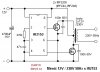
I just tried this simple circuit with a TIP41C and it looks that it is working good, better that the 555 timer circuit, so i was thinking if it can be improved a bit so it will produce full wave rather than half way rectification. I am sure also that the frequency is higher, another advantage too. Sometimes simple things are better.
Also i found this one, with this way bug zappers are working but i have not tried yet. Is there any different than the 1st one or just the same ?


Thanks
 
It Depends on if you want a Substantial POWER output, Or just more a Voltage Gain with little current?
 
AC electricity has the same amount of power when it goes positive as when it goes negative. An inverter uses a push-pull circuit with two transistors to do the same.
The simple circuits you found have only one transistor making a powerful pulse for only half the waveform so the output from the transformer is pulsing instead of making continuous AC.
 
This One will give Considerable POWER.

Mosfet-Sch-2.png
 
It Depends on if you want a Substantial POWER output, Or just more a Voltage Gain with little current?

So there is a difference right ? My goal is only to charge some capacitors up to 4-5kv, so wich one chemelec do you believe is better ? The 1st or the 2nd one ?

AC electricity has the same amount of power when it goes positive as when it goes negative. An inverter uses a push-pull circuit with two transistors to do the same.
The simple circuits you found have only one transistor making a powerful pulse for only half the waveform so the output from the transformer is pulsing instead of making continuous AC.

Yea audioguru that is true. With this simple circuit only the half waveform is used. Is there any way to use both positive and negative waveform with this way ? Maybe adding one more transistor for the negative waveform ?

This One will give Considerable POWER.

chemelec thank you for your reply but dont you think that this is a bit complicated for my purpose ? As i said avobe, i just only want to charge some capacitors at 4-5kv.


Thanks
 
Transformers work with Ac for the most part, there must be as much time x voltage above zero as that below.
The circuits you linked to are blocking oscillators, a very simple circuit popularized with Tv's, however they are only good for a few watts, if thats all you need fine.
 
transforman2, Obviously you don't need Power.
As to The 1st or the 2nd one, Not sure either one.

Probably a Fly Back Transformer Circuit to get that High Voltage.
What Size of Capacitor?

Does this need to be from a Battery?
Or are you using it in your House.
Electrostatic-Sch.png
 
Last edited:
The capacitors are x4 1,3kv-5μF in series for total of 5,2kv-1,25μF. I am planning to charge them only up to 4kv for capacitors protection. I want to be charged from batteries, i am not going to play with my home 220v.

Thanks
 
The 220 Might be Dangerous, But the 4KV Discharge from Those Capacitors Will be LETHAL.
Even though the circuit I Posted can operate from 220VAC, The HV Output is Totally ISOLATED From the Line.

To Get this HV From a battery, do a Google search for a Camera Flash Circuit.
These are usually a Double Step Up.
(So 6 or 12 volts to get 150 or 200 Volts, than this to step up again to the 4KV.)
 
Last edited:
I dont know how much a camera flash circuit can produce, i think they are powered from 1,5 or 3v.

I have another idea, What if i took a tv flyback transformer and wound the primary or adjust the voltage until i got about 4kv then just add a diode and charge the caps ? I have read that tv flyback transformers have a internal diode so maybe only just pulse AC half way would be better
 
If you do a Google Search on a "Camera Flash Circuit", You will see the schematics on how they step it up from 3 Volts to Several Thousand Volts in two stages.

SOME TV Flybacks have an Internal Diode, But Not all of them.
And most of them have Numerous Windings, Not just a Primary and Secondary.
Between that and trying to remove the Potting Material, It is Unlikely you could rewind them.

Aside from that, you can Make a Flyback from scratch.
Just need a Custom made Bobbin and some Ferrite Cores or a ferrite Rod.
I Manufacture these for another company, but the ones I make 12 VDC to 10KV.

Here is one Example:
**broken link removed**
 
Last edited:
I have a lashup high voltage supply assembled using a Tv lopty, the primary is wound around the core using just a few turns, a lot of them allow you to do this.
However the circuit is a bit more complex, it uses a smps Ic, however the o/p is regulated, not sure what the max o/p is, I set it to the most the resistor divider would take sensing the o/p voltage.
You could however do something simpler.

If I got it right the system chem was talking about uses the trigger trans in a flash circuit, the circuit charges a cap up to about 300v, then a thyristor dumps this into a trigger trans primary, causing 4 - 6kv on the trigger trans sec.
Only a few milliwatts at most will be produced, but if your using this for thermionics or something that might be enough.
 
For a transformer, you could use an old car ignition coil.

I built a rig using one of those a few decades ago with a 2N3055 as a power switch and a multivibrator to control that; it could generate a large enough arc to run a small "Jacob's ladder" device.

I used a traditional metal can oil-filled coil, this style: **broken link removed**

The new encapsulated coil packs tend to arc internally and destroy their insulation if there is not a smallish spark gap as a load, so I'd not try them without a definite load to limit the voltage.

(If you try one of those I'd start at a very low drive voltage and/or with a current limiting resistor so you don't instantly destroy your rectifiers, until you can calibrate the needed drive for an appropriate output level).
 
I have notice that adding some capacitors in the end of the AC current, there is a significant improvement in output. However i have tried some electrolytic caps and they looks like they don't last long cause they have not bee made for this purpose i guess. I have found some film caps but they usually are high in voltage and low in μF like 250v 1μF. I Have tried some various caps and i can see a better performance and output of a transformer than without it. Also for some reason it looks like the more the μf the better. Is it because my multi-meter can not read square wave or there is indeed some improvement ? Can somebody suggest me pls some caps in order to improve the output ?

Thanks
 
Last edited:
You need some low esr caps, maybe salvage some from a dead pc power supply.
The cap will turn the rms voltage to close to peak, about a 40% increase.
Low esr is needed beacuse of the frequency and peak current, 'ordinary' caps will heat up & possibly pop.
Meters usually only go to 400hz or so, measuring high frequencies requires extra expense.
 
Ok Dr pepper ty for your reply. I have seen those but all are low in μF, usually 1 to 1,5. at about 250v. Would those be enough ? Shall i put them before of after the transformer ?
 
You can get them in 1000's of uF.
They are a smoothing cap and must go after a rectifier, sounds like you want a resonant cap, they are unsuitable for that.
 
I just bought x2 IR2153 IC and i am thinking to built an inverter based on this IC. I have an attachment photo of the circuit. I would like to drive it at about 50khz frequency, but i am not sure at what values i have to change for that purpose. I found an exe file that it looks that it calculates the frequency when you put the capacitor and resistor values. According to the program with 13k resistor and 1nf cap i have about 51khz frequency, is that correct ? Also i am going to use x2 IRF540N Fets
 

Attachments

  • IR2153 Inverter Circuit.jpg
    IR2153 Inverter Circuit.jpg
    29.4 KB · Views: 286
  • Freq2153.exe
    316 KB · Views: 115
Status
Not open for further replies.

Latest threads

New Articles From Microcontroller Tips

Back
Top