im_in_asia_now
New Member
I've been thinking about how to change a DC signal (from 0 to X volts) into an AC signal (from (-X/2) to X/2 volts).
Instead of connecting the load between the DC signal and ground, I considered connecting the load between a DC signal and a second DC voltage (X/2).
Ok, so going off of a DC signal project everybody's familiar with, I tampered with a 555 circuit, using a ~50% duty cycle (https://www.electro-tech-online.com...quare-wave-pulses-have-a-50-duty-cycle.94231/) and finally came up with this:

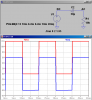
The signal is taken from between R1 and R2 and is an AC square wave at about -4 to 4 volts, where the original DC square wave is about 0 to 12 volts.
And I realise, this is just a simulation. So if this wouldn't really work in practice, by all means just let me know.

An explanation of the extra parts:
D1 is used to achieve a ~50% duty cycle
D2 is used to prevent a negative voltage on 555 pin 3 (not sure if this is even necessary, and it reduces the final output voltage)
R1 and R2 are the voltage divider network to create the AC square wave.
V2 is a negative voltage source, not sure if this will even work correctly in practice.
R3 is used to prevent a short between pos and neg terminals of the two voltage sources.
Please share your thoughts:
How much does this idea suck and what are some other ways to change a DC signal into an AC signal?
How ineffecient is this setup (where does it waste too much power) and what are the most obvious ways to improve it (if its worth improving on)?
Thanks
edit: asc:
View attachment 555 AC Square Wave.asc
Instead of connecting the load between the DC signal and ground, I considered connecting the load between a DC signal and a second DC voltage (X/2).
Ok, so going off of a DC signal project everybody's familiar with, I tampered with a 555 circuit, using a ~50% duty cycle (https://www.electro-tech-online.com...quare-wave-pulses-have-a-50-duty-cycle.94231/) and finally came up with this:
The signal is taken from between R1 and R2 and is an AC square wave at about -4 to 4 volts, where the original DC square wave is about 0 to 12 volts.
And I realise, this is just a simulation. So if this wouldn't really work in practice, by all means just let me know.
An explanation of the extra parts:
D1 is used to achieve a ~50% duty cycle
D2 is used to prevent a negative voltage on 555 pin 3 (not sure if this is even necessary, and it reduces the final output voltage)
R1 and R2 are the voltage divider network to create the AC square wave.
V2 is a negative voltage source, not sure if this will even work correctly in practice.
R3 is used to prevent a short between pos and neg terminals of the two voltage sources.
Please share your thoughts:
How much does this idea suck and what are some other ways to change a DC signal into an AC signal?
How ineffecient is this setup (where does it waste too much power) and what are the most obvious ways to improve it (if its worth improving on)?
Thanks
edit: asc:
View attachment 555 AC Square Wave.asc
Last edited: