Continue to Site

Welcome to our site!

Electro Tech is an online community (with over 170,000 members) who enjoy talking about and building electronic circuits, projects and gadgets. To participate you need to register. Registration is free. Click here to register now.

  • Welcome to our site! Electro Tech is an online community (with over 170,000 members) who enjoy talking about and building electronic circuits, projects and gadgets. To participate you need to register. Registration is free. Click here to register now.

DC motor variable speed control

Status
Not open for further replies.

garry

New Member
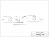
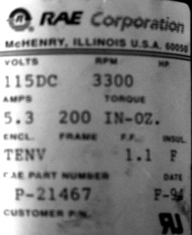
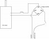
Hi, I have a DC motor that I want to make a variable speed controller for. The motor is a 115 volt, 3300 RPM, 5.3 amp, permanent magnet, brushed motor. I have it hooked up to 120 volt AC through a bridge rectifier, which seems to work well, I just need to get a variable speed control hooked up to it, as I am using it to drive a potter’s wheel. I tried a variable speed controller that I bought from Grizzly, but it didn’t work, probably because it is made for routers which are universal motors (?) and not the same as the motor I am working with. I’m not well versed in electronics, but can build to plans. Anyone have any ideas?
motorpanel-jpg.43185

dcmotorwiring-jpg.43186
 

Attachments

  • motorpanel.jpg
    motorpanel.jpg
    15.4 KB · Views: 3,294
  • dcmotorwiring.jpg
    dcmotorwiring.jpg
    8.9 KB · Views: 3,626
Hi, That motor does not seem to have very much Torque @ 200 in-oz ,you might be better off to gear it to the speed that you need with a large pully on the table and a small pully on the motor, that will increase your motor power and slow the speed down for you, make it belt driven, just my 2 cents worth :)


some info that may help
**broken link removed**
 
Last edited:
Don't you just hate it when there is a mechanical solution to an electrical problem? I don't know much about pottery wheels but i bet a 100 rpm is enough. If you still want speed control on top of the pulley let me know if you can build from a schematic.
 
Don't you just hate it when there is a mechanical solution to an electrical problem? I don't know much about pottery wheels but i bet a 100 rpm is enough. If you still want speed control on top of the pulley let me know if you can build from a schematic.

LOL Thats Funny :) I just learned too that a full bridge rectifier to change 120v AC to DC might bump the voltage up to 170V DC, Sooo be careful, Take care, Chellie
 
Thanks for the replies!
I have already built the table and pulley reduced the speed down to about 240 rpm. Most electric potter's wheels have a top speed of 240. I would like to add a variable speed control so I can slow it down as needed while throwing. The rough ball of clay is centered first at high speed, then as the pot is shaped and thinned, the speed of the wheel is reduced considerably-- the thin, wet walls of a finished pot can't take much centrifugal force.
I can build from a schematic, ronv. If you had an idea/plan of how to make a speed control, that would be great.
And the voltage bump, Chellie, I guess I can check that with a volt meter...?

found this DC motor controler :) hope that helps, Chellie

**broken link removed**

http://www.davis.com/catalog/product_view.asp?sku=7010010&pfx=


maybe this web site might be of some help, it has helped me alot :)
Power Supplies
 
Last edited:
Thanks, Chellie, those look like they would work. I guess my 5.3 amp motor is too high amps to use something simple like a rheostat?
 
Speed Control

I was about half way thru this schematic when I thought "wait, this is a dimmer". So here are 2 possibilities. One is a DIY project for about $15. The simple one is to go to Home Depot and buy a $15 dimmer to add to your bridge. Hate to admit it but the dimmer is probably better - less fun, but better. Let us know how it comes out.
 

Attachments

  • scr driver.JPG
    scr driver.JPG
    123.5 KB · Views: 1,379
Hi Garry :) I was asking these same questions too on another thread, I need a AC to DC power source for a Hydrogen generator and was asking about using a dimmer switch or a ac motor controller to adjust the voltage on the AC side using a Bridge Rectifier.


https://www.electro-tech-online.com/threads/120v-ac-to-120dc-20amps.107847/


CHELLIE View Profile View Forum Posts Private Message View Blog Entries View Articles


--------------------------------------------------------------------------------
Joined: May 2010
Location: So Calif. USA
Posts: 19
Thanked: 0 times
Will this work 120V household current to a **Bridge Rectifier 50 Amp 50A 1000V GBPC5010 AC to DC and a Electrolytic Capacitors, 1000 uF, 200 Volt, as a smoother for 120V DC ? ? ? I am making a 120v DC power supply for a HHO hyd generator, the DC current will be flowing through water with an electrolite, to produce oxy hydrogen, Thank you in advance, Chellie

Power Supplies

I remember in High School, that someone hooked up a Selenium Rectifier the wrong way to 120v AC, It shorted out and stunk up the whole class room, gee that was the worst rotten fart smell i have ever encountered LOL
Last edited by CHELLIE; Yesterday at 12:47 AM. Edit Post Reply Reply With Quote Thanks
--------------------------------------------------------------------------------
Yesterday 02:26 AM #5 bychon View Profile View Forum Posts Private Message View Blog Entries View Articles


--------------------------------------------------------------------------------
Joined: Mar 2010
Location: Florida, USA
Posts: 337
Thanked: 6 times
It is true that you can rectify, right off the power line, and the result will be almost 170 volts on your capacitors. It is true you can use that power to seperate water into HHO. Both of these processes are deadly dangerous and should not be trusted to high school students.

I don't mean to insult you. It's just that I was too stupid to manage that much dangerous power when I was in high school, and I think it's awful for people that young to be carried out in bags. Please have some old fart in charge. He/she might be able to make sure nobody gets hurt.
 
Last edited:
Thank you Ronv :) I think i can use that also on my Hyd generator Project, what value Electrolitic Capacitor would you use to smooth the DC pulses with on the DC side for the motor
 
Last edited:
Thank you Ronv :) I think i can use that also on my Hyd generator Project, what value Electrolitic Capacitor would you use to smooth the DC pulses with on the DC side for the motor

do not use a phase control for a DC motor... you need over $100 in filtering to get it to work. oh it will work, for a while. it will pump out 120 hz noise and pit out the bearings too!

you are talking about a 16mH at 10A inductor and a 2200uF lytic capable of handling the ripple current to filter a phase drive for a 5A DC motor.

Dan
 
Noise of all types

It's quite common to drive dc motors using this approach. It is true their may be a little hum under load and the electrical noise is not trivial. That's why the dimmer is a better approach because it will have filtering to make it pass FCC.
 
hate to break this to you but the circuit in the OP IS a dimmer! a standard BDC motor makes a hell of a racket and grands away it's bearings driven by a dimmer. a universal motor on the other hand might be a little better off.
 
I was about half way thru this schematic when I thought "wait, this is a dimmer". So here are 2 possibilities. One is a DIY project for about $15. The simple one is to go to Home Depot and buy a $15 dimmer to add to your bridge. Hate to admit it but the dimmer is probably better - less fun, but better. Let us know how it comes out.

Thank you, Ron. I'll give that a try!
 
hate to break this to you but the circuit in the OP IS a dimmer! a standard BDC motor makes a hell of a racket and grands away it's bearings driven by a dimmer. a universal motor on the other hand might be a little better off.

I'm guessing that a BDC motor is a brushed DC motor? Do you think it's a problem for my project, the potter's wheel, or for the hydrogen generator project?
 
I'm guessing that a BDC motor is a brushed DC motor? Do you think it's a problem for my project, the potter's wheel, or for the hydrogen generator project?

depends on how good your hearing is and how long you want the motor to last ;) I know more than most about it since my company sells a phase control DC motor control.

Dan
 
depends on how good your hearing is and how long you want the motor to last ;) I know more than most about it since my company sells a phase control DC motor control.

Dan
you are talking about a 16mH at 10A inductor and a 2200uF lytic capable of handling the ripple current to filter a phase drive for a 5A DC motor.

Dan
Sorry, Dan, most of this is Greek to me. So, you suggest that I use a 'phase control DC motor control'?
 
Sorry, Dan, most of this is Greek to me. So, you suggest that I use a 'phase control DC motor control'?

actually i recommend you use PWM ... phase control will burn out the motor bearings unless you put a huge filter on it. if you want to filter the PWM it takes smaller parts since you are at higher frequency. 16-20KHz is common. if you use a filter with 100KHz you can use reasonable parts for filtering - around 50uH and 10uF where as at 120Hz (60Hz full wave rectified gives you 120Hz at the motor/filter) you need 16mH and 2200uF

Dan
 
SCR Driver

Interesting that the company that makes Gary's motor also makes a similat controller.

**broken link removed**
 
Interesting that the company that makes Gary's motor also makes a similat controller.

**broken link removed**

That is a lamp dimmer with a couple limit pots and a rugged thyristor, and it WILL wear out the motor bearings. 200% current limit? BS! once a TRIAC fires there is NO CONTROL until the cross over allows it to turn off! And I do not see anything resembling an IC to do the actual control ... there is not even room enough there for a stupid little 8 pin chip

worst case is at 50%. think about it... you have a motor at half speed and every half cycle you apply 170V to the motor. that effectively slams the shaft into the bearings 120 times a second.
 
Status
Not open for further replies.

Latest threads

Back
Top