Continue to Site

Welcome to our site!

Electro Tech is an online community (with over 170,000 members) who enjoy talking about and building electronic circuits, projects and gadgets. To participate you need to register. Registration is free. Click here to register now.

  • Welcome to our site! Electro Tech is an online community (with over 170,000 members) who enjoy talking about and building electronic circuits, projects and gadgets. To participate you need to register. Registration is free. Click here to register now.

DC/AC Inverter project, need some help with design

Status
Not open for further replies.

JBatt

New Member
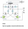
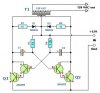
I have been trying to build a 12VDC to 120VAC voltage inverter for some time now, and came up with this design a while back. I have tried building it several times, but All that happens is the wirewound resistors start putting out extreme amounts of heat, and no voltage output. The attached image contains the schematic.

Also, I have tried reversing the polarity of diodes D1 and D2, removing them completely, and using several different types. Still nothing.

Is it possible that some parts are defective, or is there a flaw with the design? I'm open to suggestions and modifications to my design.

Note: C1T and C2T are tantalum electrolytics, R1 and R2 are ceramic-cased wirewound resistors.
 

Attachments

  • inverter_276.gif
    inverter_276.gif
    4.1 KB · Views: 8,613
Hi JBlatt,

Hmm ...

You have the caps backwards.
And why have you got diodes across transformer windings?

I think you should remove the diodes, and their resistors.
Check the remaining components are ok,

And you may find that the 12v windings are a far lower
impedance than you realise.
They should take up around half of the window space to
act as a primary winding.
And since you are using them half at a time,
maybe they should take up a bit more than half.

Those considerations wouldn't stop it working,
but would badly affect its efficiency.

Also, check that your two windings are connected as you
think they are,
if one is reversed, you would get no output,
You may have a pair of wires for each 12v winding,
The two ends you join to make the middle connection
have to be the right ones.
Difficult to say from here.

Best of luck with it, John :)
 
the 68 mfd caps look a bit large to me ?
and the 180 ohms seem very low to me ?

I would choose a base resistor which gave me between
a volt and one half a volt on its winding, without the
caps in place, that is most of the supply voltage
across the 2N3055, and just a small voltage across its
associated winding.

And the same for the other 2N30055 and its winding also.

At a guess, maybe you have chosen the 180 ohm resistors
in the style of 'Class A output'

In a switching circuit like this, that is not necessary.

Maybe others would care to say how they would set up
the biasing ?

Regards, John :)
 
Actually, I did not design this circuit, "came up with" was a bad choice of words. I actually found this cirtuit on the internet quite a while ago, and this was how it was set up-- diodes included, and the caps in that direction. I'll try breadboarding a modified one tomorrow with the caps hooked up the other way around, and the diodes/10w resistors gone. Thanks for the suggestions, will post how it works when I get the chance.
 
I beg to differ, but I think the capacitors are the correct way round.

The capacitors are large and the 180 ohm resistors are small to give the 2N3055s sufficient base current (consistent with oscillating at around 60Hz), because their gain is not high and they are driving reasonably large currents. The alternative to this is employing driver transistors, which would complicate the circuit.

I think the diodes and series resistors are designed to snub out back EMF from the transformer primary which could destroy the transistors.

If you have tried reversing the diodes, you may have destroyed them. Check them with a DMM.

Tantalum capacitors are not tolerant of being reversed nor of overvoltage, so check them too - you might find one or both are short circuit. If you replace them, ordinary electrolytics might be better.

In fact, I suggest you check all the components before switching on again - there aren't many, and all are straightforward to test with a cheap DMM.
 
Hi,

I had a look around on the internet, and i found this:
**broken link removed**
I will attach the circuit shown from this.

It is not identical, but it is so strikingly similar that
its clear to me this arrangement is a working design.

As Mr Partridge has said, it looks like the caps are correct
as drawn (sorry about that), although it seems there was
some confusion about that from this source too.
Positive to the base, in each case.

The author of this piece also goes on to say that the caps
have to be tantalum, but doesn't really say why, other than
standard electrolytics aren't up to it and may explode or
fail. My guess is that the ripple rating needs to be quite
high.

I still don't really see why diodes are included across the
windings, but there it is.

JBatt,
as your inverter is still not working, i would suggest you
check carefully the direction of each 12v winding.
It seems this circuit is a practical working design, and i
can only think that your windings may not be correctly
direction-ed.

Other than that, theres component failure, or a wiring fault.
There aren't that many parts to check, as Mr Partridge says.

Best of luck with it, John :)
 

Attachments

  • Inverter.jpg
    Inverter.jpg
    21.3 KB · Views: 8,235
Ive been thinking about those diodes,
could it be that any current they pass,
adds to the flux on that half-cycle?

as q1 passes current, and its winding gets some volts across it,
the opposite winding would get some volts too, and the diode/
resistor would turn that into current, presumably to augment
and add to the flux from the current through q1.

And q2 would do the same.

Is this a possibility ... or am i dreaming again ?
 
Alright, for purely experimental purposes, I am replacing the two 68uF caps with two large high-load 330uF 200V caps from a PC power supply (I have plenty of them, and can get them very cheap is why I'm using them.) Going to try breadboarding the circuit with just that changed, and see how it works. Also am substituting 1N1007 diodes for the 1N504's.

BTW, the transformer I am using is a 12v-0v-12v secondary 2amp transformer from Radio Shack, forgot to mention that in my original post.
 
So if you have a single connection for the centre of the winding,
then we have to assume that the windings are correctly oriented.

But if you have two wires for each of the 12 volt windings and
you have to join two wires to make the centre point then we must
ask you to make sure that the windings are correctly oriented.

Your last post did not make this clear.
 
Nothing happened, no voltage output from either side of the transformer. I'm convinced that the transistors are blown, will post back when I can get a few replacements. (checked them with a DMM, no continuity between base and emitter, either polarization)
 
I recommend: try with darlingtons, and give a small assymetry for base-bias.
 

Attachments

  • Inverter_124.jpg
    Inverter_124.jpg
    18.5 KB · Views: 8,070
Don't change the value of the capacitors - it will change the frequency at which the circuit runs.

Did you test your 2N3055s using the diode check range on your DMM? Most DMMs put out less than 0.6V on the ohms ranges so you will see open circuit even for good transistors. But the diode check range will put out a high enough voltage to forward bias any diode junctions. And it tell give you the voltage drop rather than a resistance reading.

Check B-E and B-C in both directions. You should read 0.54V or thereabouts when the red probe is on B, and open circuit when the black probe is on B. Also check between C and E for punch-through - should get open circuit both ways.
 
Ive posted about that same invertor circuit in another forum and i have some words of caution. Using electrolytic capacitors in that circuit can be
very dangerous. The currents flowing in that circuit can cause the electrolyte to boil . A 200V 330uF capacitor can explode with quite a force, have you ever seen a small capacitor explode? I saw it happen once when i was in college and it was quite a bang !

And John , Andrew is right about the the diodes across the center-tapped transformer. They are there to protect the circuit from back emf from the windings, nothing else. And its very important to have them there. The collapsing magnetic field around the transformer windings will induce a backward voltage or counter emf into the secondary, as well as the primary. The diodes will safely shunt or desipate this voltage away from the driving electronics.

You may have also noticed that theres a resistor connected in series with each of the diodes, that should give you some idea of the amount of power that the diodes are shunting.


Net.
 
Check your transformer ..

The easiest and least expensive way to get a large T1 is to re-wind an old microwave transformer. These transformers are rated at about 1KW and are perfect. Go to a local TV repair shop and dig through the dumpster until you get the largest microwave you can find. The bigger the microwave the bigger transformer. Remove the transformer, being careful not to touch the large high voltage capacitor that might still be charged. If you want, you can test the transformer, but they are usually still good. Now, remove the old 2000 V secondary, being careful not to damage the primary. Leave the primary in tact. Now, wind on 12 turns of wire, twist a loop (center tap), and wind on 12 more turns. The guage of the wire will depend on how much current you plan to have the transformer supply. Enamel covered magnet wire works great for this. Now secure the windings with tape. Thats all there is to it. Remember to use high current transistors for Q1 and Q2. The 2N3055's in the parts list can only handle 15 amps each.
This circuit can be tricky to get going. Differences in transformer ,may cause it to not function
 
I need help to finish this project.

Hai ! I am Hon from Malaysia. i have problem with the 68uf tantalum capacitor. There is no 68uf tantalum capacitor sell by electronic component shop in my state , so i try it by using regular 330uf 200v capacitor.as a result, the capacitor explode.


I need help from someone to buy & send the 68uf tantalum capacitor for me and i will pay for it please.

Thank you!!!
 
I have seen the same circuit posted on several sites and have built and re-built it exactly to spec. I cannot get the circuit to output <100vac. The first few seconds I plug into the ciggarette lighter, It outputs about 115vac and rapidly diminishes down to about 30vac. The caps and the transistors both get EXTREMELY hot. Whats the problem with this design. :?:
 
What were you using as a load ?

The output voltage is effected by how much current the load is drawing.

With 12 volts driving a transformer that steps up the voltage to 120 volts, the current will be stepped down by the same proportion.

So, for example, if the current in the "primary" is 1 amp @ 12 volts the current in the "secondary" will be 1/10 of a amp @ 120 volts, and this is considering a 100% efficiency for the transformer.

Also when a load is applied to the output of the transformer the circuit "sees" this as a higher resistance (or impedance) and the voltage/current in the secondary drops off.

Yes the components will get very hot which is why it is suggested that the power transistors be mounted to a heatsink of the proper size and in some cases to add a cooling fan as well.

It appears to me that the circuit is very inefficient and needs some means of regulation.
 
I dont think the caps should get hot.
 
I didnt have a load on the AC side besides my voltmeter. I was leary to plug anything into it before i tested for the correct voltage. As far as the caps getting hot, that could possibly be transfering from the transistors. If i use a higher output transistor, will they not run as hot? or by increasing the transistors am i basically also raising their output propotionally? Im assuming so considering what you were saying (nettron) about having no regulation.
 
I didnt have a load on the AC side besides my voltmeter. I was leary to plug anything into it before i tested for the correct voltage.

Hmmm...that is odd. You said you had it powered from the cigarette lighter in a vehicle, was the motor running at the time ? Im thinking maybe it wasnt getting enough current, but i doubt that.

Perhaps theres an intermitent problem with one of the components when they heat up , i'd suspect the power transistors. Try cooling them down with a fan ( a can of compressed air would be ideal ) and at the same time measure the voltage output of the transformer.


if i use a higher output transistor, will they not run as hot? or by increasing the transistors am i basically also raising their output propotionally?

Yes they may run as hot or prolly even hotter but the heatsink would have to be bigger to compensate for this but i dont think thats the issue. All Power transistors are low gain devices but some have slightly more gain than others. They are primarily power gain devices, meaning they are designed to handle high current loads.
Im wondering if anyone as ever tried using power MOSFET's in this circuit, they have a higher efficiency than bjt's.
 
Status
Not open for further replies.

Latest threads

New Articles From Microcontroller Tips

Back
Top