Continue to Site

Welcome to our site!

Electro Tech is an online community (with over 170,000 members) who enjoy talking about and building electronic circuits, projects and gadgets. To participate you need to register. Registration is free. Click here to register now.

  • Welcome to our site! Electro Tech is an online community (with over 170,000 members) who enjoy talking about and building electronic circuits, projects and gadgets. To participate you need to register. Registration is free. Click here to register now.

Datasheet For This part

Status
Not open for further replies.

AtomSoft

Well-Known Member
eh i feel dumb doing this but i need help finding out the info for this part:
 

Attachments

  • count.png
    count.png
    650.8 KB · Views: 300
It's an optical interuptor. One side is an LED, the other side is a photo diode or transistor, should be able to work what's what by looking at the circuit.
 
So it just counts am i right?

I can see which side is the diode through the markings on top. How do i connect the photo diode on the other side? (it has 2 pins) should i like pull it high and then when ever the pathway is clear it connects the pulled high side to the PIC?
 
So it just counts am i right?

I can see which side is the diode through the markings on top. How do i connect the photo diode on the other side? (it has 2 pins) should i like pull it high and then when ever the pathway is clear it connects the pulled high side to the PIC?

**broken link removed**

ken
 
I have a cool idea with this optointerrupter. you will see it on the Microcontroller forum soon! :D

How about that chip i know its memory but i cant find a datasheet
 
The other chip is a 16 bank 1mbit (128kB) sram chip. Didn't try to look for the PDF too hard but it's useful if you can interface to it.
 
Last edited:
lol yeah its a 180 ohm lol
The OptoInterrupter has 5k resistance on the transistor side. Is that normal?

Sceadwian:
I wish i knew how to interface to it also :D
 
Last edited:
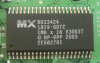
For and SRAM chip like that Atom, unless you can find PDF's easy, ditch it, they're cheap to buy new with full support, and you can get them in DIP form factor still, though I somehow don't think you're afraid of surface mount =)

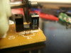
5K sounds normal to me, is it on the emitter or collector side?
 
Last edited:
I tested across the pins.

I might just ditch it but its fun using parts taken from something else lol. Im going to add the interrupter to the GLCD project and have it add a pixel every time it goes on/off. This way it runs left to right top to bottom on the screen.

Maybe even do the same as above but drawing a picture. So its like every toggle it will add a byte to the screen from a image. Im a very bored person as you can see :D

I have to step out for a little. Got called to fix a PC, gonna get $150 to do the job. I gota reinstall XP and Setup the small 2pc network. Easy work :D
 
Notice how many slots are in that wheel, you could easily swamp a PIC wither interupts if you spun the wheel quickly, just keep that in mind.
 
Last edited:
heh im back :D just made some Sony (SIRC) code for a receiver in C. I used to think it was the hardest thing to do. And now that i got it to work without even reading a datasheet i feel like god lol.

I was going to use it to draw a pixel using a normal :
cPin = CountPin = RB0 or something lol
Code:
if(cPin == 0)
    setpixel (global_Y++,global_X++);

And just have it skip what ever it misses. As long and it counts it and goes all the way to the end :D
 
Or you can use one of the PIC's timers in counter mode. ;)
 
Depends on if the timer is synchronous or not, depends on a lot of things actually, like how fast you need to spin the wheel, what resolution you want and the frequency of the pic (if it's synchronous)
 
So Jason...

How many hours a week you spend on this stuff? :D

I got the look from my wife today she said "wish I could spend that much time on a hobby..."
 
Depends on if the timer is synchronous or not, depends on a lot of things actually, like how fast you need to spin the wheel, what resolution you want and the frequency of the pic (if it's synchronous)
He'd have a hard time overwhelming the hardware timer on a PIC with a mechanical wheel and Opto encoder. Most of the PIC frequency counter projects, which work up to 40-50Mhz, use the hardware timer and prescaler at much higher frequencies than AtomSoft will ever see from his encoder wheel.
 
Status
Not open for further replies.

Latest threads

New Articles From Microcontroller Tips

Back
Top