Continue to Site

Welcome to our site!

Electro Tech is an online community (with over 170,000 members) who enjoy talking about and building electronic circuits, projects and gadgets. To participate you need to register. Registration is free. Click here to register now.

  • Welcome to our site! Electro Tech is an online community (with over 170,000 members) who enjoy talking about and building electronic circuits, projects and gadgets. To participate you need to register. Registration is free. Click here to register now.

DATA transmission/receiving using SCR Radio modules.

Status
Not open for further replies.

camerart

Well-Known Member
Hi,
I would like to be able to send/receive data, using radio modules.

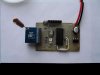
I'm using CHIP MODULES with Semtech SX1278 CHIPs on them.

Cheers, Camerart.

SX1276-7-8-9PDF link: https://www.semtech.com/images/datasheet/sx1276_77_78_79.pdf

The program/circuit below use the SX1278 simplest? setup as it only switches the radio ON/OFF, as a test for the system so far.

The program on POST#149 is the finished but un-tested program written in LORA EXPLICIT HEADER MODE.
 

Attachments

  • 18LF2520 SX1278.jpg
    18LF2520 SX1278.jpg
    198.4 KB · Views: 378
  • 18lf2520 8mHz INT OOK TX BOOST 160617 1400.txt
    8.7 KB · Views: 333
Last edited:
Have you considered the HC12 modules?, they aren't cheap but they are VERY easy to use (just simple serial IN and OUT), and offer much greater range.

I've used a number of them recently, and I've been VERY pleased with them.
 
Hi,
The program in #1 is for RFM22 modules. I've been told that the later, more interesting modules, such as RFM69W, are quite different and from a different manufacturers.
Does anyone know if the program in #1 (which simulates, but I don't think is working properly) would modify for RFM69W or do I have to start again?
C.
Have you considered the HC12 modules?, they aren't cheap but they are VERY easy to use (just simple serial IN and OUT), and offer much greater range.

I've used a number of them recently, and I've been VERY pleased with them.

Hi N,
I did! I have chosen the RFM range as they are frequency programmable, and are more sophisticated (I think) than the HC12 modules. Time will tell:)
It's a tall order programming them though, let's hope it's worth it.
C.
 
I have chosen the RFM range as they are frequency programmable

So are the HC12 modules, from 433.4-473.0MHz, and adjustable power, up to 100mW.

and are more sophisticated (I think) than the HC12 modules.

In what way?, and what are you wanting them to do?.

As far as simulating what you already have, as you've got the modules why not do it for real? - that's the ONLY way to know if the code is really working or not.
 
So are the HC12 modules, from 433.4-473.0MHz, and adjustable power, up to 100mW.

In what way?, and what are you wanting them to do?.

I did say "I think"

[QUOTE="As far as simulating what you already have, as you've got the modules why not do it for real? - that's the ONLY way to know if the code is really working or not.[/QUOTE]

I've been finding out as much as I can about any modules. The modules I have are RFM22 on OrangeRX radio control transmitters, so I chose RFM, as someone must have chosen them for the Orange ones. However the RFM22 modules are now outdated and RFM69 (They are in the mail) appear to be the ones to choose. They have a system called LoRa for longer distance, but at the moment it's a bit advanced for me, although I could change the program later.

For me, I like to watch the program processing in the Simulator, that's why I am doing it, while my modules arrive. I need to start with someone else's program, then adapt it for Oshonsoft. (not easy)

The OrangeRX modules work as radio control TX and telemetry return RX, is this possible with HC12?

C.[/QUOTE]
 
The OrangeRX modules work as radio control TX and telemetry return RX, is this possible with HC12?

They work basically as a wireless RS232 link, it's as simple as that - in fact you can develop your project using a wired connection (Txd, Rxd, and Gnd) and then simply replace the cable with the modules.

So no problem returning telemetry, or anything else you want.
 
They work basically as a wireless RS232 link, it's as simple as that - in fact you can develop your project using a wired connection (Txd, Rxd, and Gnd) and then simply replace the cable with the modules.

So no problem returning telemetry, or anything else you want.

Vot a salesman. I've got 3x on order, see you in 6weeks:)
C.
 
Hi,
While waiting for the HC12 modules, I'm hoping to still use the SX1276 modules, I have also ordered. I can compare them then.
Eric and Roger have sent information for adding SPI into my program, which is based on an 18F4520 PIC.
C.
 
Hi,
Here is the code:
SPIPrepare '>>>>>>>>>>>>>>>>>>>>>>>>>>>>>>>>>>
SPICSOn
SPISend $0a 'this is the address of the reg you want To Write too.
WaitUs 10
SPISend $05 'this is the data that will be written to that address
SPICSOff
WaitUs 20

It looks as though it's working. Is it simply, the first SEND after SPICSON is the ADDRESS and the second SEND within ON/OFF is the DATA?
Is there a way of 'seeing' what's going out of the SEND PIN?
C.
 
Is there a way of 'seeing' what's going out of the SEND PIN?
hi,
Use a Scope on an actual PIC or if in sim use the Tools/Scope
E
 
hi,
Use a Scope on an actual PIC or if in sim use the Tools/Scope
E
Hi E,
So it does, thanks:)

I've got 16 pages of registers, with 1million register addresses. Most of them have a default setting. Is it ok to just switch on the module and these defaults are set? Then if anything needs changing, e,g, frequency etc then change the register?

I'm a bit puzzled by how to set the frequency e,g, 435MHz Here is a snap of a program showing frequency setting:

EDIT: Penny dropped!! 0x6c8000 = 7110656
61.035 * 7110656 = roughly 433998888 hz = roughly 434Mhz

C.
 

Attachments

  • Setting frequency.jpg
    Setting frequency.jpg
    40.4 KB · Views: 416
Last edited:
Hi,
Updated 18F4520 program in #1 which produces the
The JPG shows ADDR2 and DATA2 = (regopmode, standby) = 00000001 and 10000001


C.
 
Last edited:
Is there a way of 'seeing' what's going out of the SEND PIN?
Hi C , I have been using a pair of HC-12 for RTX data without much problem ( other than my own C code ! ) a PIC24 either end.( @ 8 MIPS ) if you can send serial between PIC's , then moving to HC12 should not be a big problem, I have a small "cats whisker " serial LCD that helped , just attached it to any of TX or RX pins to see what I sent was what I received. One thing i have found with PIC UART's is that you need to have an interrupt driven FIFO buffer at each end, as it were, each byte received gets put in the buffer and sets a flag ( HC_input =1 ) the main(); flow then jumps to a service routine that takes the bytes from the buffer clears the flag waits for next byte . I send an ID h'AA then 20 packed BCD bytes terminated with an h'FF. ( other terminators are available :) I have seen messages formatted like a print stream , with CR, NL, or null .
G.
 
Hi G,
See posts#10,12,and13.

I'm deep into programming 18F4520 PIC that will control SX1276 modules at the moment, and must keep my blinkers on :)

If you remember will you remind me again #15 and I'll re-look into HC12s, I've got some in the post.

C.
 
Status
Not open for further replies.

Latest threads

New Articles From Microcontroller Tips

Back
Top