Continue to Site

Welcome to our site!

Electro Tech is an online community (with over 170,000 members) who enjoy talking about and building electronic circuits, projects and gadgets. To participate you need to register. Registration is free. Click here to register now.

  • Welcome to our site! Electro Tech is an online community (with over 170,000 members) who enjoy talking about and building electronic circuits, projects and gadgets. To participate you need to register. Registration is free. Click here to register now.

Damaged PCB power rails

Status
Not open for further replies.

Doomguy42

Member
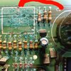
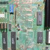
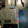
I'm working on repairing an old PCB where a CMOS battery has leaked. After repairs and cleaning up I'm measuring 71Kohms between the 53v and 12v rails (no continuity)
I do alot of battery damage repairs but because wanted to check people's thoughts on the leakage because it's between the power rails which is new.

Should I be concerned? Using ohms law it works out in the mA range (53v has a 10amp fuse?) It could be through components?

Any advice welcome

Thanks
 
Thanks for the reply, interms of the leakage do you think its anything to worry about? Will the +12 be contaminated to much or do I need to go on the hunt around the board?
 
LIke Diver300 said - is it reading through the components?. If you haven't removed ALL the components that connect to those two rails, you're not checking the PCB, you're checking the components.

I'm a little 'horrified' at a ten amp fuse on a 53V rail - what is the unit?.

Can you post a picture of the board?.
 
I haven't removed all the components.

I'm testing through the power loom pins but I suppose I could make 2 cuts further down the rail before the components to just check the repaired rails? There are tons of darlington transistors probably 40 odd components to remove. The 53v is for flashing lamps on an arcade style fruit machine. Yeah these boards were notorious for burning up. The battery ground pin was notched into the 53 with ardly any clearance!

Yeah... the first pic Is the damage. The rails are close together at the top. It's very old and rare so worth working on.

Pic 2 is the board about 50% cleaned up. The remnants of the rails I removed after this. The surface is scraped back too so there's no contaminated mask across the surface e

Pic 3 my repaired rails. I've fixed on new copper rails using epoxy. The board is wet from ipa in the pic. It's a work in progress still.

Pic 4 is a different board but shows how my repairs end up. Sealed in and insulated.

I know it's not ipc standards but I like doing it like this rather than a mass of wires on the back. It's just the 53v I'm worried about. All of these boards are BER but it's just for the challenge I work on them
 

Attachments

  • 20220905_204221784.jpg
    20220905_204221784.jpg
    1.9 MB · Views: 155
  • 20220919_235648555.jpg
    20220919_235648555.jpg
    1.8 MB · Views: 155
  • 20221109_214827392.jpg
    20221109_214827392.jpg
    2.6 MB · Views: 154
  • 20210908_234929.jpg.fb0191c3cbd0c3ed79fbbb8b48ae2585.jpg
    20210908_234929.jpg.fb0191c3cbd0c3ed79fbbb8b48ae2585.jpg
    229.7 KB · Views: 157
Last edited:
Do you have an identical board that works?, if so compare it with the faulty one.

However, with the components in place it's fairly likely that you will get resistance readings between the rails - through the components down to chassis, then back up through other components to the other supply rail.

Assuming you've cleaned off all the corrosion, then the board shouldn't be leaking - IPA and a stiff brush soon sorts that out.

Aren't batteries a pain for this sort of damage though - as are some types of electrolytic capacitors, which cause similar havoc.
 
Yeah batteries are a pain, it's great when they come back to life. I have one other board but it's worse so I can't really use it for measuring.

Thanks... guess I just needed a second opinion.

Is there any maths I can learn for working out the voltage or current gains to the 12v? Just out of interest?
Ohms law, if there's really a leak between the rails? - but it should be easy to tell (to some extent).

Put the probes back on the rails, so it reads as before, then leaving one in place, move the other one to the chassis rail - does the reading increase or decrease. Then go back and do the same, but moving the other probe.

If the readings decrease, the the leakage is simply through the components - as expected. If it increases, then the leakage is through the board.

To help you understand, the picture below shows the reasoning. From 12V to 53V it will read 71K (the two resistors in series) and from 12V to Gnd it will only read 35K, or 36K from +53V to Gnd. In your case the values are unlikely to be half of the original value, but they should both be lower, and add up to pretty much the same.

Resistor_Leakage.png
 
Status
Not open for further replies.

Latest threads

New Articles From Microcontroller Tips

Back
Top