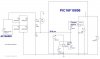
Hello, Will we potentially damage our PIC16F18856 by setting it up to do mains zero crossing detection as in the attached schem?
We have a 40W offline , non-isolated LED lamp. We have a PIC16F18856 in it which has circuitry to do zero crossing detection (ie circuitry inside the micro itself) . Therefore, we set it up as in the attached schem to do mains zero cross detection.
However, we are not sure if this is OK?...after all, the Microchip datasheet and App Note examples never show mains zero crossing detection…but only show examples where the AC source that’s being “zero-cross-detected” has the same reference ground as the PIC16F18856.
……In our case, the AC source being “zero-cross-detected” is the mains, and obviously its not referenced to the same ground as the PIC16F18856.
Do you think we could potentially damage our PIC16F18856 by connecting up the PIC16F18856’s zero cross module in the attached shown way that we have?
My post on the microchip forum about the Zero crossing detector inside the PIC16F18856…
https://www.microchip.com/forums/m1006813.aspx
PIC16F18856 datasheet
(ZCD module on page 305 )
https://www.microchip.com/wwwproducts/en/pic16f18856
Microchip App Note on ZCD module….
https://ww1.microchip.com/downloads/en/AppNotes/90003138A.pdf