Continue to Site

Welcome to our site!

Electro Tech is an online community (with over 170,000 members) who enjoy talking about and building electronic circuits, projects and gadgets. To participate you need to register. Registration is free. Click here to register now.

  • Welcome to our site! Electro Tech is an online community (with over 170,000 members) who enjoy talking about and building electronic circuits, projects and gadgets. To participate you need to register. Registration is free. Click here to register now.

D flip flop

Status
Not open for further replies.

kinarfi

Well-Known Member
In a recent thread, D Flip Flops used two resistor to bias the D input, one to Vcc and one to Gnd with the switch in the middle. Is the resistor go Gnd necessary? If so, why?
 

Attachments

  • 3.png
    3.png
    26.8 KB · Views: 247
Having just experimented with this recently, all you need is a resistor between the pin (CLK in this case) and ground. (Should be a fairly high value, >10K. 20K is good. You don't want it to draw power.) The switch should simply go between V+ and the pin. The resistor keeps the input from "floating" when the switch is off. No need for the 2nd resistor. (In other words, lose R1.)

Have you thought at all about debouncing the switch? I'm trying to do the same thing--use a pushbutton to clock a string of D flip-flops, and I still have not solved the problem of debouncing. Search threads for a discussion of RC debouncing, using Schmitt triggers. They're absolutely necessary. Otherwise you're going to get nothing but totally flaky behavior.
 
Last edited:
Interesting spice simulations, used the circuit pictured above after removing R2 and measured current while the load was turned off, -182.304pA, then I replaced R2, removed R1, moved switch to vcc instead of gnd and moved the transistor base to Q instead of Qnot and measured the current again, -187.828pA, uses 5.5 more pA.
I haven't messed with debouncing yet, I'll wait until I actually have the problem, an scr may lend it self to the cure some how. My frequency will be something in the neighborhood of one button push in the morning and one in the evening.
Kinarfi
 
Do you mind explaining what this circuit is doing? Also, is there need to have two transistors to light up the LED? It just seems like you could get away with putting the LED on the collector and making the 20k to 400ish to drive the LED. But I must be missing something.....
 
R3 is the load, it requires a power transistor (Q2) to drive it. The led is just an indicator to show when the output is on. The circuit is missing a base resistor for Q1, and it needs a power on reset circuit to insure that it gets reset to the off condition at power up.
 
Last edited:
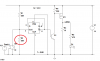
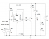
Thanks for answering, Brevor, The flip flop drives Q1 which controls R4 which controls M1, a power MOSFET which supplies current to my load, the LED is only a statis indicator. The load is a filter setup to power my amplifier for my head sets and a 12 - 5 volt LM317 for my GPS. The USB plug for my GPS used to be on 24/7, but if it got wet, it would corrode severely because of the voltage on it, so, I decided to make it so it could be turner off and I used a push button and flip flip to turn it of and practice using flip flips and P FETs. A toggle switch would be simpler, but not as fun. Also, the flip flop circuit is powered up 24/7 and the switch is pushed once or twice a day and sometime not for weeks.
Kinarfi
 

Attachments

  • 4.png
    4.png
    35.9 KB · Views: 187
Last edited:
Status
Not open for further replies.

Latest threads

New Articles From Microcontroller Tips

Back
Top