Continue to Site

Welcome to our site!

Electro Tech is an online community (with over 170,000 members) who enjoy talking about and building electronic circuits, projects and gadgets. To participate you need to register. Registration is free. Click here to register now.

  • Welcome to our site! Electro Tech is an online community (with over 170,000 members) who enjoy talking about and building electronic circuits, projects and gadgets. To participate you need to register. Registration is free. Click here to register now.

Custom PWM reference controller?

Status
Not open for further replies.

Cole

New Member
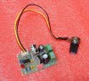
Currently I have 10 fans inside my gaming pc. 2 are OEM fans that plug directly into the motherboard into separate 4pin (PWM) fan headers. The other 8 fans I have added myself. To power the extra fans I purchased a PWM motor controller (picture 1), and wired the input terminals to an extra power connector coming from the PSU (12v). This setup has been working great for months. Based on CPU temp the computer controls (the 2 fans) fan speed via PWM. So, for the other 8 fans, instead of having to turn a knob (POT wired to controller) I would prefer to somehow tap into the OEM PWM circuit (to allow the computer to control all fans based on CPU temp). I understand that I cannot simply tap into the OEM fan wires, due to the amount of current being drawn by the other 8 fans will overload the circuit. So is there a circuit/module similar to the one I purchased that uses an input wire to reference and existing PWM signal instead of a POT? Basically to copy the PWM but using power being supplied directly from the PSU.
 

Attachments

  • Picture 1.jpg
    Picture 1.jpg
    340.8 KB · Views: 201
Hi Cole,

We need a bit more information about your set up:

How does the computer control the standard fans. Does the computer pulse width modulate the fan power or does the computer modulate the fan pulse width modulation input.

If the later is the case, which is normal, and your additional fans have pulse width modulation inputs the chances are that you can connect all the fans to the pulse width modulation output from the computer as it will be a logic level signal and the pulse width modulation input to fans are normally a relatively high impedance.

That sounds a bit convoluted so I hope it makes sense to you.:)

spec
 
Last edited:
I believe that nearly all computer motherboards I know of have a separate PWM pin for controlling the fan speed. That 555 controller from your image looks like it would just PWM the power to the fan, which is doable, but not ideal.

First, you need to figure out what kind of fans you have:

Fans with 3 pin connectors will typically have GND, +12V power, and a fan speed sensor. Rather than controlling the fan's speed, this just reads the number of pulses from the rotation inside the fan's motor (usually using a Hall effect sensor, I believe), which can then be read by a software program or through the BIOS.

Ideally, you will want fans with 4 pin connectors: GND, +12V, speed sensor, and PWM control.

untitled2.JPG


From there you can just graft the PWM inputs of the other 8 fans onto the PWM control pin of the CPU fan. As Spec mentioned, the input impedance of each of the fans is probably quite high (such as that of a CMOS input gate), so connecting several in parallel probably won't be an issue. I don't recommend connecting all the fans to the same power pins, though, as that would be quite a lot of current for a single Molex-type pin to handle, especially in such a mission-critical location as your CPU fan.

If all your fans are 3-pin or even 2-pin (just power and GND), then you are going to need to get a bit more technical and connect a buffer in series with the PWM output from your MOBO and use the PWM signal to switch the power rails of your fans. A high side driver ship, or a level shifter to a power MOSFET would probably do the trick. You may need to add in a back-EMF diode to protect against the voltage spikes from switching the fan motors on and off-- I'm not sure if those come standard in computer fans or not.

Lemme know if you follow all that or have questions. I'm not always terribly good at toning down my techno-jargon. :D

Also, I'm assuming you already know this, but unless those fans are REALLY quiet, 10 fans going full blast once your CPU heats up is going to be rather loud...
 
Last edited:
Most PCs have two different styles of fan connectors (fan headers); 3 pin (-, +, and tach out) (runs fans at constant 12v no PWM) (no PWM controller built into fan), and the other style 4 pin (-, +, tach out, pwm) (PWM controller built into fan). I understand what you're saying, i didn't think of that, but the 8 fans I have added are 3 pin as appose to the two OEM 4 pin fans that vary speed based on CPU temp. So because the 3 pin fans are able to be PWM controlled, but the computer itself does not pwm them, I assume that the extra pin/wire in the 4pin is to send a reference/signal to the integral circuit board inside the fan itself to pwm the fan motor. So is there a controller that can do what the 2 fans do, take the blue wire signal from computer and create a pwm signal output (to fans) ?
 

Attachments

  • 20170206_130019.jpg
    20170206_130019.jpg
    772.8 KB · Views: 177
Yes, exactly. If all your fans are 3-pin, then what you are going to want to use is a "high side driver," either as pre-built chip or made from discrete components like MOSFETs, and use the PWM signal from your motherboard (taken off of the blue wire on your CPU fan) and use that to drive the +12V rails on your other fans.

You could do it either as 8 individual drivers-- one for each fan, or one big driver for all 8, or some combination depending on the current draw of your fans and the rated current of whatever driver you use. The grounds can just be connected together to the negative of your PSU. The sense pins aren't that important unless you want to know the fan speed of each individual fan, otherwise they can just be left floating if you want.

For bonus points, you might hook up an Arduino or something to measure the fan speeds.

Edit: actually, in retrospect, there is no reason you can't use a low side driver, either.
 
Ok that makes sense. I would prefer to purchase a pre-built chip, where would I go about finding one? if not, I could make it myself, but I don't have any of the parts or knowledge of which ones I need.

Most of the fans I have snipped the "tach out" wire already, but the Arduino idea sounds awesome (again no experience with them).

Oh and I know the picture wont help with any technical info, but here is my computer (the LED strips run on same parallel circuit as fans)
 

Attachments

  • 041.jpg
    041.jpg
    931.3 KB · Views: 144
There are many wholesalers of electronics parts that hobbyists use, such as Digikey, Mouser, and Allied Electronics to name a few, but for just a few chips you may be able to find stuff on more mainstream sites like Amazon or Ebay if you search "high side driver IC" into the search bar.

From there, look at what part numbers are available and look up the datasheets for those parts. They will usually have all the ratings and specifications, as well as example schematics on how to connect everything when you solder it up.

...er, um, I guess I should have asked earlier, but you are okay with having to solder stuff, right? You'll probably also want some solderable perf board, and be sure to get DIP-package or TO-220 (power transistor package) parts. I would occasionally order surface mount parts by mistake when I was starting out.

Snazzy looking rig you got there. Gotta love Dells and their crazy left-hand mounted motherboards, but where are the fans going to go?
 
Yes soldiering things are fine. You would recommend building it as appose to buying a prebuilt?

Yeah I love the left side mobo mount design. The fans are already in (PSU, case exhaust, pci exhaust, northbridge, ssd, etc.). I've been running the 8 fans using the PWM controller I purchased for a few months now, just decided that I want the computer to vary fan speed, not me.
 
No real recommendation one way or the other really. Your call. There might be some kind of prebuilt kit for this, but I just don't know what's available. Ebay is usually your best bet for cheap kits like that. The real trick is trying to work out what keywords will get you to what you want. Even then, they might not be pre-assembled, and you'll have to solder together the components onto a pre-made PCB. Usually not too hard, and good soldering practice if you ask me.

If you design/make something yourself, I suspect most of these driver ICs will only require a small number of support components, or perhaps almost none at all. I guess you will need to do your research and determine what would work best for your application and skill level. I suppose some might consider hand-soldered protoboards in their gaming rig to be unattractive, but if it were me, I would wear it like a badge of honor. :cool:
 
Last edited:
It's still not clear if your 8 "other" fans are 3 or 4 pin fans. If 4 pin then it's simply a matter of running the motherboard pwm signal to them along with power.

Mike.
 
Mike, the other 8 are 3 pin. So they don't have the ability of self-PWM, they need either ground or power to be pwm by a controller. The issue is finding a controller that has signal input (most have POT) So the controller itself can mimic/mirror/copy the pwm going to the 2 OEM fans, while operating on a separate power lead. I will most likely be building it from parts such as the ones JLNY suggested. Any suggestions?
 
It might be cheaper to by 8 four pin fans. Last time I bought any they were AUD6 each!!

Mike.
 
BTW, surely, the power supply fan should not be controlled by the motherboard temperature.

Mike.
 
Well the fans I have in it now are perfect and I do not wish to change all the fans. The OEM power supply fan had less than 15 cfm. The fan I replaced it with at full 12v has 45cfm, Even at minimum PWM, it provides more airflow than stock fan at 100%.
 
POST ISSUE 3 of 2017_02_07

Well the fans I have in it now are perfect and I do not wish to change all the fans. The OEM power supply fan had less than 15 cfm. The fan I replaced it with at full 12v has 45cfm, Even at minimum PWM, it provides more airflow than stock fan at 100%.
Hi Cole,

Right got your position.

So, in summary, you would like to route the PWM logic level signal from the computer and drive a separate power driver that pulse width modulates the 12V to the auxiliary fans.

This can be simply implemented by one low gate threshold power NMOSFET transistor, one 1N400x diode, and one resistor, as shown below.

spec

2017_02_07_ISS1_ETO_PWM_FAN_CONTROLLER_V2.png
 
Last edited:
I thought Cole already had a PWM driver board that he was using to control all 8 fans, and that setup was presumably working. Is there any reason he can't just use the PWM signal from the motherboard to control the driver board he already has? It could feed into pin 4 of the NE555, and the timing capacitor could be shorted to make the NE555 act as a buffer. This is assuming that the output stage of that board is an emitter-follower configuration; it not, then a transistor inverter can be used.
 
I thought Cole already had a PWM driver board that he was using to control all 8 fans, and that setup was presumably working. Is there any reason he can't just use the PWM signal from the motherboard to control the driver board he already has? It could feed into pin 4 of the NE555, and the timing capacitor could be shorted to make the NE555 act as a buffer. This is assuming that the output stage of that board is an emitter-follower configuration; it not, then a transistor inverter can be used.
Yes, good points- why didn't I think of that.:)

But you may find that using a power NMOSFET is simpler in the end.

spec
 
Yes, good points- why didn't I think of that.:)
But you may find that using a power NMOSFET is simpler in the end.
spec
Yes, a single FET that operates at logic levels, and maybe a free-wheeling diode is also pretty darn simple. PWM frequency is apparently around 25 kHz.
 
Last edited:
HI D83,

I have now posted the schematic in post #17 showing a circuit along the lines we discussed.

spec
 
The issue is finding a controller that has signal input (most have POT)
If you smoothe the PWM with a simple RC filter you get a voltage. Won't the POT type controller accept that as equivalent to the pot wiper voltage?
 
Status
Not open for further replies.

Latest threads

New Articles From Microcontroller Tips

Back
Top