Continue to Site

Welcome to our site!

Electro Tech is an online community (with over 170,000 members) who enjoy talking about and building electronic circuits, projects and gadgets. To participate you need to register. Registration is free. Click here to register now.

  • Welcome to our site! Electro Tech is an online community (with over 170,000 members) who enjoy talking about and building electronic circuits, projects and gadgets. To participate you need to register. Registration is free. Click here to register now.

current zero crossing detector

Status
Not open for further replies.

Mojalco

New Member
hi! im planning to build a power factor meter using the phase difference of the zero crossing of the voltage and the zero crossing of the the current. I think I will be using a 89c51 microcontroller. My voltage zero crossing detector works fine as I can see it in the oscilloscope, (60hz in 16.6666ms) but I was not able to have a satisfying result with my current zero crossing detector. By the way, Im trying to measure a load at a maximum power of 25KW.

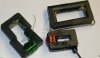
Im getting my signal from a current transformer(150:5) and fed it to a schottky rectifier and amplify the signal by means of an LM324 op amp.

Anyone has a better idea?
Your help will be much appreciated! thanks in advance!
 
Hi
I had the same problem last year, until I find the solution.
Use AC to RMS converter chip instead of Zero crossing detection.
My final project wasn't to high tech, I used an old monitor flyback core to make my own current transformer, and the voltage measured from a miniature power transformer, removed from portable AM/FM radio.
I hope this help.
:idea:
STEVE
 

Attachments

  • AC2RMS.gif
    AC2RMS.gif
    13.5 KB · Views: 2,220
  • currentT.jpg
    currentT.jpg
    12 KB · Views: 1,689
Cool, but he wants to measure power factor. I think you missed the point, csaba.
 
Schematic Diagram of my existing setup for PF measurement

Here is my preliminary circuit design for the PF measurement.
I'm measuring phase displacement between V and I to get my PF.
The circuit performance is not acceptable since the supply I got
was varying in frequency,depending on load (58-63Hz). I based my design on a 60Hz :(

Are there any approach which doesnt consider frequency variations?

Thanks.
 

Attachments

  • ZeroCross_205.gif
    ZeroCross_205.gif
    20.2 KB · Views: 2,075
supply voltages for LM324

The supply voltage for IC2 is 5 volts and the supply voltage for IC4 is 9V.
 
Re: supply voltages for LM324

Mojalco said:
The supply voltage for IC2 is 5 volts and the supply voltage for IC4 is 9V.
That's what I thought. You need a negative supply for your op amps, because you are trying to work with signals around ground. For example, the output of IC2A can never go to GND, so the input of IC2B will never cross the threshold.
You need to add some protection for the input of the 74LS04, because IC2B is going to overdrive the input in both directions after you add a negative supply. You can add a 1k resistor in series, with 1N4148 diodes to +5v and GND. One diode will have the cathode to +5v and the anode to the 74LS04 input. The other diode will have the cathode to the input and the anode to GND.
 
re:dual supply for op amps

Thanks for the advice. I'll do it right away. I'll just let you know the results. I assume that I'm in the right direction because I was beginning to doubt my design and I'm starting to to entertain some other ways of measuring power factor. :)
 
Status
Not open for further replies.

Latest threads

New Articles From Microcontroller Tips

Back
Top