stryker1080
New Member
Hi everyone, I am a mechanical engineer who is in need of help! I am designing an underwater flashlight which will be using Luxeon high power leds. I have found a driver circuit which uses FET and NPN transistors and i was hoping someone can help me disect it a bit.
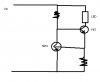
I have done a bit of research so i have a basic understanding of how NPN and FET transistors work, but i was hoping someone can just clarify a few things. I have attached the circuit drawing.
Basically at the end of the day, i want to limit the current going through the LEDs to 1A. My understanding of how this circuit is supposed to work is this:
- The bottom right resistor is chosen so that when maximum wanted current is going through it, the voltage drop is equal to the "turning on" voltage of the NPN (ie. ~.5V) . So I need a I=V/R => 1 = 0.5/R = > R = 0.5 Ohm
- When the circuit draws too much current, the NPN transistor opens up and the current goes mainly through the NPN transistor instead of the FET and it limits the current? THe reason i have trouble understanding this is because i read that FET transistors are voltage regulated, and in order to minimize the curretn going through the FET a -ve voltage is needed?
- How do you calculate the voltage drop going through a transistor? Is there any voltage drop?
- How do you select the resistance of the Top Left resistor?
- When the NPN transitor opens up, wont all the current go though it instead of the FET and completely shut off current going through the Load? How would this work as a self-adjusting circuit?
Hopefully someone can describe in detail what is going on with this type of circuit, i apologize for my lack of knowledge. I have been searching and reading the forums to piece together knowledge to find out how this is supposed to work.
Thanks!
")

