Continue to Site

Welcome to our site!

Electro Tech is an online community (with over 170,000 members) who enjoy talking about and building electronic circuits, projects and gadgets. To participate you need to register. Registration is free. Click here to register now.

  • Welcome to our site! Electro Tech is an online community (with over 170,000 members) who enjoy talking about and building electronic circuits, projects and gadgets. To participate you need to register. Registration is free. Click here to register now.

Current limiting with LM317

Status
Not open for further replies.

Muni

New Member
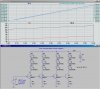
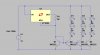
I want 10.8V with limited current (80mA) from 12-28V input supply. I tried with LM317T as a current limiter circuit but it starts limiting only from 13V or so. When I reduce input voltage below 13, both the current and voltage at the output go down. Any one please advise me how can I get 10.8V @ 0.08A at 12V input.
Thanks
Muni
 
A current limiter circuit works by reducing the output voltage until the load draws the limited amount of current.

Since you want 10.8V at 80mA then your load must not be less than 10.8V/80mA= 135 ohms.

An LM317 needs an input that is 2V to 3V higher than its output plus 1.25V additional input voltage to supply voltage for the current-limiting sensing resistor. Your 12V input voltage is too low.
 
Try the LM1086 for lower dropout.

At 80mA you might be able to get away with the LM317.

A 100mA polystitch can be used for over current protection.
 
Current limiting circuit with LM317

Actually I wanted to connect 4 rows of WLEDs, 3 in series in each row at 20mA. I wanted to limit this current at exactly 80mA (4 rows x 20mA) with the cheaper circuits. My source is a 12V 7Ah battery. Please advise me if you have any idea which I can go for least cost.

Thanks Ron for your suggestion, I will try with LM1084.
Muni
 
It's generally best to use a single current limiting device per chain, diodes in parallel are bad enough without multiple diodes in series and parallel the voltage forward won't match closely enough with series+parallel chains. At the very least you'll need current balance resistances in series with each string as well as the main current limit.
 
Actually I wanted to connect 4 rows of WLEDs, 3 in series in each row at 20mA. I wanted to limit this current at exactly 80mA (4 rows x 20mA) with the cheaper circuits. My source is a 12V 7Ah battery. Please advise me if you have any idea which I can go for least cost.

Muni

Muni,

here is something I simulated using LTSpice. The x axis in the plots is the battery voltage. The upper plot shows the current through one of the diodes, and the power dissipation in one of the NPN transistors. The lower plot shows the battery voltage and the voltage at the collector of the transistor. Note how the difference between these two traces remains constant.

I'm using the nominal 1.25V output from a LM317 as the reference voltage which drives the four bases. The current through the diodes is controlled by the emitter resistors. The circuit will have some temperature dependence.
 

Attachments

  • 4ChanCurrentReg.jpg
    4ChanCurrentReg.jpg
    326.4 KB · Views: 1,570
I had a somewhat similar idea to MikeMI, except I configured the NPN transistors as current mirrors. In this config, the LM317 is acting as a current source ONLY. There is no voltage regulation, only current regulation. You can allow the input voltage to fluctuate from 10.8V all the way up to 28V and the LED current will stay between ~19ma and ~22ma per string, which should be perfectly fine regulation for an LED. In this sim I used an LT1086 because I couldn't find an LM317 in the LTSpice database, but it should swap in just fine.
 

Attachments

  • LED array.asc
    1.8 KB · Views: 548
  • untitled.JPG
    untitled.JPG
    43.2 KB · Views: 4,834
Current limiting circuit with LM317

Thank you both, MikeMI and Speakerguy79, for your valuable information. I had used similar circuit as Speakerguy79 used but LM317 instead LT1086. I will try now with LT/LM1086 and let you know.
Finding proper parts in Nepal is very hard. Thus it may take me some weeks to find LM or LT1086.
Thank you all helping me in the forum.
Muni
 
Did the LM317 not perform correctly? The LT1086 only has a lower dropout voltage, otherwise they are more or less equivalent.
 
If you're just using the LM317 as a reference, there's no point in using the LT1086 as it doesn't need to be a low-drop-out regulator.
 
I had a somewhat similar idea to MikeMI, except I configured the NPN transistors as current mirrors. In this config, the LM317 is acting as a current source ONLY. There is no voltage regulation, only current regulation. You can allow the input voltage to fluctuate from 10.8V all the way up to 28V and the LED current will stay between ~19ma and ~22ma per string, which should be perfectly fine regulation for an LED. In this sim I used an LT1086 because I couldn't find an LM317 in the LTSpice database, but it should swap in just fine.
Speakerguy, that's a great idea for getting the current source overhead out of the dropout equation. I'm concerned that the matching might not be so good in hardware. The current mirror works pretty well in an IC, where emitter areas, saturation current, thermal gradients, etc., can be tightly matched. With 5 random transistors out of a bin, it might not work so well. You could add a 10Ω 1% resistor in series with each emitter and get better current matching, with little loss of headroom. You get the added benefit of more stable current vs supply voltage.
If anyone has actually built this circuit, I would like to know how well the currents match, especially when one of the current sources has its transistor replaced with a number of randomly chosen units with the same part number. I may be all wet - but I don't think so.:D
 
I misread the schematic, I can see what's happening now, it's a current mirror, not just a using the LM317 as a voltage source.
 
You are right Roff, the 10ohm emitter degeneration resistors would be a good idea. I was honestly wondering how much of an effect beta would have, as I've never bothered measuring it within a batch (honestly because good people like you point out that an emitter resistor would be a good idea, and make the design a lot more independent of beta :) ). There are also more complex type current mirrors that are more beta independant, but that would add some additional transistors.
 
You are right Roff, the 10ohm emitter degeneration resistors would be a good idea. I was honestly wondering how much of an effect beta would have, as I've never bothered measuring it within a batch (honestly because good people like you point out that an emitter resistor would be a good idea, and make the design a lot more independent of beta :) ). There are also more complex type current mirrors that are more beta independant, but that would add some additional transistors.
I don't think beta is nearly as important as Vbe matching. I'll run some more sims. The sims I ran only varied Vbe (which I changed by varying m, which is the emitter area multiplier.
 
Well you are working harder at this then and know more than I do :) I have long since forgotten device modeling like with the hybrid-pi model and whatnot. I just though the basic current mirror idea was an easy way to not have to worry about voltage regulation and set the current at the same time.
 
Last edited:
Well you are working harder at this then and know more than I do :) I have long since forgotten device modeling like with the hybrid-pi model and whatnot. I just though the basic current mirror idea was an easy way to not have to worry about voltage regulation and set the current at the same time.
For transistors with identical characteristics except for emitter area, the diode equation will predict current ratio as a function of ΔVbe. This is fairly accurate for multiple monolithic transistors, but there are two other variables (Is, N) in the equation that make it tough to use it for discrete transistors. Simulations are pretty good at predicting potential problems, but there is nothing like hardware to get the real answers.:)
 
And on that note, LEDs have a very soft forward curve and can be paralleled easily if they are the same brand/batch. You can further match them by measuring the LED Vf with a multimeter diode test.

If you have 2 or more LEDs in series they are even easier to parallel.

I would have made a constant current driver with 2 transistors, to power the whole array of LEDs. Voltage dropout is not much more than 0.6v, the last one I made with BC327 transistors had a V dropout of about 0.8v at full current driving the LEDs.
 
mmmmmm interesting, so you would place a resistor in each string plus the transistor in the output of the volt reg?, so you would have 5 for a 4 string circuit.

it looks that this would disipate less power than a volt reg ....
 
mmmmmm interesting, so you would place a resistor in each string plus the transistor in the output of the volt reg?, so you would have 5 for a 4 string circuit.

it looks that this would disipate less power than a volt reg ....
Total power dissipation for LEDs driven by any sort of linear regulator (voltage or current) will be the product of the unregulated supply voltage times the LED current, plus any overhead current used by the regulator (usually not too significant). You can only get around this by using a switching regulator. If you use a linear regulator, you can minimize wasted power by choosing an AC stepdown transformer that provides the minimum voltage required while still being high enough to prevent loss of regulation.
 
Last edited:
Status
Not open for further replies.

Latest threads

New Articles From Microcontroller Tips

Back
Top