Continue to Site

Welcome to our site!

Electro Tech is an online community (with over 170,000 members) who enjoy talking about and building electronic circuits, projects and gadgets. To participate you need to register. Registration is free. Click here to register now.

  • Welcome to our site! Electro Tech is an online community (with over 170,000 members) who enjoy talking about and building electronic circuits, projects and gadgets. To participate you need to register. Registration is free. Click here to register now.

Current flow indicated by led.

Status
Not open for further replies.

protowerks

New Member
Hi All,

What i'm trying to do:
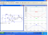
I would like a led to light when i insert two probes into water, the 'probe circut' is powered by a 3.7v lithium ion battery and there is approx 800 microamps flowing when then probes are in the water.

Could you give me some help with a basic circut that will allow me to detect current flow in the 'probe circut' and then switch a led on please?

Kind regards,

Andrew
 
Hi,

You need to amplify your current/Votage, then use a comparator to turn your LED ON/OFF.
 
current sense

This should work.
Either your probes are close together or you have some good stuff in your water.:)
 

Attachments

  • probe.PNG
    probe.PNG
    78.9 KB · Views: 196
Thankyou ronv!
please excuse my lack of knowledge - are the 'ref' and 'probe' additional probes that need to be present or are they just labels?

sorry for my lack of understanding...

Thank you

Andrew
 
Hi ronv,
I've made up the circuit but i'm having a small problem - as soon as i connect the battery the led comes on with the probes out of the water - would the type of led i'm using play a part in this?
(I'm using rs components part numer 4664030 )

Thankyou

Andrew
 
I dont see how the circuit can work with R4 in the circuit. R4 is holding the non inverting pin high and hence led on.
If the probes were where R4 is then it might work.

Would not a simple transistor have worked as a amplifier to switch the led on, thats all i have used in the past.

Pete.
 
No, Not an led problem.
Actually Pete is right. A transistor would do it if it's just a go no go thing.
Having said that, the circuit should work.
With the probe out of the water the + terminal of the comparator should be 3.696 volts while the - terminal is 3.663 volts. This will vary depending on the battery voltage but the + will always be more positive than the negative. Thus the output should be + and the led off.
With the probe in the water the + terminal will be lower than the - terminal and the led should come on.
 
I'm seeing 3.75 on the pin 4 -ve input and 3.79 on pin 5 +ve input with the probes out of the water
When i put them in the water pin 5 +ve input is dropping to from 3.79v to 3.74v - this should be lower?

How can i increase this drop?

Thanks,

Andrew
 
Hmm. Should work with those numbers. Is the led off with the probe out of the water?
You can center it a little better by making R4 a bit larger - say 470 ohms.
 
Thanks ronv,

led is on when probes are out of the water - maybe i've put the led in backwards... but this should mean that when i put the probes in the water the led should go off? it stays on...

I will try the 470 at r4 and see how i go...

Thank you again..

Andrew
 
Any time pin five is more positive than pin 4 the output should be off and the led should go out. So that's the place to start.
It's an LM339 and 3.7 volts on pin 3 and ground on pin 12?
 
yep LM339N on the chip

3.7v on pin 3 pin 12 to gnd

using pin 2 connected to led through resistor and pins 4 -ve input and pin 5 +ve input

With the 470 in R4 im getting a change from 3.77 to 3.47..

I'll take some measurrents from pin 2 - output
 
I may have given you a value for R1 that was to low and zapped your LM339.
Lets start over.Make R6 & R3 47K
Make R2 47K and R4 27K
Make R1 150 ohms.
This will give a much higher voltage swing on the inputs and lower current for the led.
 
I agree with Pete; a transistor would be simpler. However, if you want to use the comparator circuit then try R6 = 22k and R4 = 10k. That will increase the drop.

Alec
 
I failed to notice ronv's revised figures in message #16 above. Those should do the job too ;-)

Alec
 
Status
Not open for further replies.

Latest threads

New Articles From Microcontroller Tips

Back
Top