Electro Tech is an online community (with over 170,000 members) who enjoy talking about and building electronic circuits, projects and gadgets. To participate you need to register. Registration is free. Click here to register now.
Welcome to our site! Electro Tech is an online community (with over 170,000 members) who enjoy talking about and building electronic circuits, projects and gadgets. To participate you need to register. Registration is free. Click here to register now.
Yu can use any clock less than the maximum, in fact for a PIC you can go right down to a DC 'clock'. If you're using the in-built oscillator, you have to alter the config fuse settings - HS for high speed crystals, and XT for crystal - however, there's no clear division where you should swap over. Cetainly 20MHz is HS and 4HMz is XT, I would suggest trying HS above 10MHz.
For your goldcard, as far as I'm aware, they use an external clock - fed in on one of the card pins - so you simply require an external 8MHz oscillator feeding the correct pin, and set the PIC to use an external oscillator.
I'm not very clear about what you'r plugging the goldcard into, I presume from this it's something containing a PIC?.
There used to be a technical bulletin at MicroChip, showing you how to use one xtal to run two PIC's, from what I remember you basically just connect the output of the one with the xtal, to the input of the other.
As this is going to be on a card, through a socket, you may need to buffer the oscillator output of the PIC with the xtal.
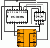
(in the card RB6= conected to the external clock line. pin 12 (16F84a)
the problem is that i need to program all the stuff with compilers and they don't accept Xtal =2 or 1 soo i cant use the normal Fosc / 4 function
expect if i clock it @ 16Mhz..and that number is accepted soow that could be a solution or not??
Obviously there's not a great deal of choice, as there are only RB6 and RB7 available, but generally one would be used as a serial input, and the other as a serial output. My tutorials give suitable code to do this, although you may need to adjust the bit timing depending on your clock speed.
If you wanted to do bi-directional serial I would suggest using a pull-up resistor on the line, and both connections set as inputs. To initiate a serial transmisson the sending device changes it's pin to an output, and pulls it low - this becomes the start bit for the serial transmission. Once it's done sending data the pin is returned to an input again.
or should i just make a simple pin hihg low timing part???
if i just grab a 20Mhz cristal how should i connect that one to the card??
1 pin of the crystal to vdd (5volt) and the other to the input on pic??
You can't add a crystal to the card, you need an external oscillator - this is usually provided by the cardreader circuit it plugs in to.
Do you have some reason for wanting to use a 20MHz clock?, PIC's usually send almost all of their working life sat wasting time - so unless you have an urgent need for maximum speed 4MHz is usually plenty.
because the other chip use it also has (16F818/9) if i will use the internal ocs it will be 8 if output it it will be 2?? 2 my compiler doesn't accept. i can buy a 4Mhz external one that will help.
back:
soow i loaded a test prog in it
RB7 high for 1 sec and then low for 1 sec etc..
it works
but!!
you forgot one thing i think.
RB6 is conected to pin 16 on the card soow if i use that one for serial comm my OSC input goes wrong right??
soow i only have 1 wire to communicate.
i don't untherstand wy the hell they didn't use some more contacts on the card to the other pins... :cry: :cry: :cry:
what would you suggest for 1 wire communication....?? a simple timing routine?? or would you do some communication routine??
i need to do something soow it is unique..
maybe i didn't tll its a wafer type card..soow i don't have acces to the chips..
p.s. one thing i already learnd is you have to put RB6 to input mode if you don't it will be high and then it braks the osc input signal...
basicly rb6i only used for programming.
RB7 is then left for comm.
TKS
p.s. if i code protect the card it isn't possible to read the code right? now one exept microchip maybe???
because the other chip use it also has (16F818/9) if i will use the internal ocs it will be 8 if output it it will be 2?? 2 my compiler doesn't accept. i can buy a 4Mhz external one that will help.
I'm a bit confused by that?, the input and output are the same frequency, it's the internal clock speed which is 1/4 of the crystal - everything external is at the full crystal frequency. It's VERY common for the internal processor to run at a fraction of the clock speed, almost all do - the Z80 ran particularly slow.
If you have one PIC running with a 20MHz crystal, and link it's output to the clock input of the goldcard, then the goldcard will run at 20MHz as well (and internally at 5MHz - just like the first one).
back:
soow i loaded a test prog in it
RB7 high for 1 sec and then low for 1 sec etc..
it works
but!!
you forgot one thing i think.
RB6 is conected to pin 16 on the card soow if i use that one for serial comm my OSC input goes wrong right??
The usual point of them is to use a standard communication protocol, so it can connect with a standard card reader - it's what the card does with the data that's important - not the communication link.
What are you actually trying to do?.
maybe i didn't tll its a wafer type card..soow i don't have acces to the chips..
Yes, if it's set as an input it's high impedance, and won't affect the clock, if it's an output it's low impedance (if it's high, or if it's low), this will obviously kill the clock signal.
It's certainly not easily possible, if you search hard enough you can find various schemes for breaking protection on any processors, but PIC's are probably as secure as most.
This site uses cookies to help personalise content, tailor your experience and to keep you logged in if you register.
By continuing to use this site, you are consenting to our use of cookies.

 (16F818/9) if i will use the internal ocs it will be 8 if output it it will be 2?? 2 my compiler doesn't accept. i can buy a 4Mhz external one that will help.