Continue to Site

Welcome to our site!

Electro Tech is an online community (with over 170,000 members) who enjoy talking about and building electronic circuits, projects and gadgets. To participate you need to register. Registration is free. Click here to register now.

  • Welcome to our site! Electro Tech is an online community (with over 170,000 members) who enjoy talking about and building electronic circuits, projects and gadgets. To participate you need to register. Registration is free. Click here to register now.

CRT repair for idiots

Status
Not open for further replies.

Joelsplace

New Member
I collect cars and do all my own work. I picked up a Hunter tire balancer with a CRT monitor. Everything appears to work except the monitor is dead - does nothing.
2020-08-26 15.56.48.jpg

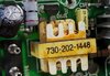
A visual inspection revealed a burned Toshiba C5339 and a swollen 1000uf 25V capacitor. The components are on opposite sides of the board so I don't think the 2 problems are related. The capacitor is in a section of the board that is labeled 12V.
What kind of information do you guys need to tell me what direction to go with this repair?
The C5339 is mounted to a large heat sink but the compound is totally dried up and the board is discolored. What else should I check before I burn up some new parts? Thanks!
 
The C5339 and 2SC5339 are popular horizontal output transistors which would make sense with any CRT type device. You may want to give this a read:
HORIZONTAL OUTPUT TRANSISTOR BLOWS UP - REASONS (CRT Based TVs). A big part of the problem is you are likely looking at a symptom, a blown up horizontal output transistor and not the root cause of the problem or why it is toasted. Replace the cap and less the transistor try turning the system on and look at your DC voltages. The cap looks to be a common 1,000 uF 25 WVDC filter cap. Less any drawings and a good knowledge of how these things work it will not be easy to trouble shoot it.

Ron
 
Pins 1 & 3 are shorted to ground measured at the board with the C5339 removed. You were correct in that the C5339 burning out is just a symptom.
The transformer has has 3 pins and 2 wires. The three pins show .1 ohm between any pair with my cheapo meter. The 2 wires show .6 ohm between them. Does this mean it is shorted? That seems like a really low reading.
 

Attachments

  • 2020-08-26 16.58.32.jpg
    2020-08-26 16.58.32.jpg
    175.8 KB · Views: 167
Last edited:
1, 2, and 3 if I read it right should be Base, Collector and Emitter so if that holds true the Base and Emitter are shorted to ground. The transistor is a NPN type so Emitter to Ground is not that unusual depending on how they have it configured. To turn it on when running the base needs to be at least 0.7 volts more positive than the emitter. When taking resistance readings you also may want to try the leads one way and then reverse them because you don't know what other semi conductors you may be forward or reverse biasing when you probe.

Ron
 
Pins 1 & 3 are shorted to ground measured at the board with the C5339 removed. You were correct in that the C5339 burning out is just a symptom.
The transformer has has 3 pins and 2 wires. The three pins show .1 ohm between any pair with my cheapo meter. The 2 wires show .6 ohm between them. Does this mean it is shorted? That seems like a really low reading.

That's because it's the primary of the line driver transformer, so perfectly normal.

Main cause of LOPT transistor failure is the LOPT transformer failing.

Basically, unless it's a chassis you're VERY familiar with, you replace the transistor and see if it goes BANG when you turn it ON - keeping a close eye, and ear, on the LOPT transformer (they commonly arc internally, or externally, and blow the transistor).
 
The transformer has has 3 pins and 2 wires. The three pins show .1 ohm between any pair with my cheapo meter. The 2 wires show .6 ohm between them. Does this mean it is shorted? That seems like a really low reading.
that's normal, however, if you noticed the small transistor next to the transformer, that's the primary side of the transformer.... on that side of the transformer, look for a small (usually somewhere between 4.7uF and 22uF, and rated between 16V and 50V) electrolytic capacitor connected to the opposite end of the primary than the small transistor. replace that capacitor as well, and any electrolytic coupling caps between the secondary and the 2SC5339 base pin. problems with either (sometimes there isn't any coupling cap, but the driver transformer bypass is important) can cause the output transistor (the C5339) to overheat. when i was in the business of repairing CRT monitors, it became habit to replace these capacitors if i had a repair involving a shorted horizontal output transistor. and make sure you use white(not silver) heat sink grease for the output device.
 
Thanks for all the help. I had to work a job out of town yesterday and didn't have a chance to look at it. I have about an hour right now so I'll check for the capacitors. I do have a capacitance meter and an ESR meter so I can check them.
Please explain the problem with using silver heat sink compound. From what I understand it works better. I thought the only time you shouldn't use it is when there is a problem with it being conductive. I have both but I would like to understand why.

That capacitor on the primary side was 100uf 35v and it only measured 14uf. I replaced it. Thanks!
 
Last edited:
One thing I did forget to mention - resolder the joints on the driver transformer - a common cause of LOPT transistor failure was dry joints on the driver transformer.
 
Yay! We like happy endings. :)

Ron
 
Well it worked for several hours the other day when I thought I had it fixed and today when I turned it on the brightness was way too high. I turned it down with the screw on the flyback and it worked for 10 minutes or so and then went out. I turned it off and right back on and it came on for about 15 seconds and then went out - no display at all.
It was 106 the other day when it was working. Now it is 86 degrees. I checked the C5339 when it was working on the 106 degree day and it was running about 126 degrees.
The capacitors I installed were used because that is all I had but they measured ok. Maybe that bit me?

Update: I let it cool down and tried again with the same results. The 3 larger transistors on the "neck board" if that is the right term get up to about 200 degrees. When the display went dark this time I used compressed air to cool down the transistors and really the whole board and it came back on. Now it has been running several hours without any trouble. ??? I've turned it off and on several times also. The only difference is the ambient temperature has slowly risen from 86 to 97 degrees. Maybe it likes hot weather.
 
Last edited:
I thought the only time you shouldn't use it is when there is a problem with it being conductive.
that transistor a rather high voltage component, don't take any chances... if you hadn't noticed, heat sink grease sometimes gets onto things you don't want it on. a tiny smear of it between the collector pin and the back of the transistor can cause problems. the silver stuff is primarily for CPU heat sinks, not high voltage transistors...
 
Status
Not open for further replies.

Latest threads

Back
Top