Continue to Site

Welcome to our site!

Electro Tech is an online community (with over 170,000 members) who enjoy talking about and building electronic circuits, projects and gadgets. To participate you need to register. Registration is free. Click here to register now.

  • Welcome to our site! Electro Tech is an online community (with over 170,000 members) who enjoy talking about and building electronic circuits, projects and gadgets. To participate you need to register. Registration is free. Click here to register now.

Criticize my PCB!

Status
Not open for further replies.

darkfeffy

New Member
Hi all,
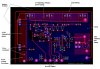
I am trying to build a 3.75kVA buck converter with synchronous rectifier switched at 100kHz. Please criticize this PCB (attached photo) without fear or favour :mad:. I have tried to annotate as much as possible. Switching is done at 100kHz.
Something keeps bothering me...in some literature power planes are discouraged. In others they are encouraged. A third group says it depends...In this case, what is recommended?
Thx
Edwin
 

Attachments

  • Buck power planes.JPG
    Buck power planes.JPG
    150.3 KB · Views: 194
A 3750W single phase buck regulator? it's not going to work. besides, 52V @ 100A is 5.2kW which is even worse!

First, if you have 220Vac, why not just transform it down to a more manageable level and convert from that point?

If you go through with building this, that board is going to fry along with all the power components. The FETs are placed way too far apart so there are killer parasitics all over the board. The amount of copper for the amount of current is severely lacking. The gate traces are way too thin. I could go on but there really is no point - you need to rethink your approach.
 
Thought I should add that the <311V, 33Amp> power plane is the input and the <52V, 100A> is the output.
Regards
Edwin
 
if you haven't done a smaller version of it, try to do that first. this is very high power / high frequency stuff and I am not sure if you can get it right the first time.

as to ground plane, they act like a giant capacitor and for high di/dt applications (yours is surely one such application), you don't want them, or if you do, be extremely careful with them.
 
Where are you getting PCB connectors that handle 100A (AWG 2) through a single pin? Where exactly is your 100A inductor going to be connected? Your inductor will have AWG 2 leads which need a holes of 0.2576" plus clearance. Are C8 and C13 your 100A filter capacitors? Are these caps the standard type with 24-26 gauge (2-3 ampere) leads?

As for your PC board, my calculations suggest that you'll need 10-oz copper front and back to keep temperatures reasonable. (If the other parts exist.)

If J9 is your input GND and J10 is your output GND then the bottlenecks between them are unacceptable.

There is no cap made in the size of C19 and C20 that could filter 33A.
 
You'll probably use a 50A fuse to protect the 33A input. What wire size will it have? It looks like J11 and J12 are pretty small, like 0.025"??. That tiny piece of 0.025" wide trace by Q3 will incinerate instantly when you apply 33A. After you fix that, the 0.050" trace between Q1 and Q2 will begin to smoke. GND under R1, R2, R3 etc is pointless. Use the space to optimize the high current traces.

Print out a couple of copies of your layout. Take a contrasting highlighter and mark the current path. Mark one for the switching phase and one for the recovery phase. Note the following:
1) Current density. Is there enough copper? No exceptions, no excuses. When a part is carrying 50A, you should reconsider thermal relief.
2) Have you allocated a large enough space? (1µF on 33A is ludicrous.) (10µH 100A is not 1 in².)
3) Is the current path shared by small signal devices? You must isolate these paths! Ground current must not flow through small signal "ground".
4) Extra credit for EMI: Is the current path similar for the switching and recovery phases? The bigger the difference, the greater the EMI (and you might be the victim of your own EMI. :eek: )
 
That was some great criticism...
Think I'll have to seriously cut down the power requirement for a start...
And get some decent heat sinks.
Merci
Ed
 
Status
Not open for further replies.

Latest threads

New Articles From Microcontroller Tips

Back
Top