Solder Guy
New Member
The power supply of my Creative A520 speaker system got nuked in lightning. I tried an external adapter 12V/1Amp and it works with occasional volume loss during heavy bass. I guess the adapter is unable to supply enough current.
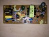
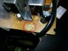
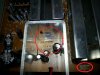
I am trying to repair the power supply but cannot figure out the values of the burnt parts.
I can see two resistors and a zener diode as burnt:
Please help me figure it out.

I am trying to repair the power supply but cannot figure out the values of the burnt parts.
I can see two resistors and a zener diode as burnt:
Please help me figure it out.
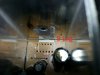
 . I think your best hope is to find someone with the same model supply and get the values from that. There's a good chance the IC is fried too: the board near its pins looks to have delaminated? Can't spot any datasheet for that IC in a quick search.