Continue to Site

Welcome to our site!

Electro Tech is an online community (with over 170,000 members) who enjoy talking about and building electronic circuits, projects and gadgets. To participate you need to register. Registration is free. Click here to register now.

  • Welcome to our site! Electro Tech is an online community (with over 170,000 members) who enjoy talking about and building electronic circuits, projects and gadgets. To participate you need to register. Registration is free. Click here to register now.

Correct relay for my project...

Status
Not open for further replies.

Renato

New Member
Hello all,

I am hoping that a correct relay will be able to help me with my project. I have tried 2 different relays and I can not get it to work... Also, I need to use the smallest possible 12 V DC relay. I have used Omron's G5A- relays.

Here is the scenario that I am trying to get working.

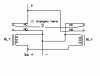
1) I need a relay that will take +- one time and the next time the signal will be -+. Polarity changes with each momentary signal.

2) I have 2 12V diodes, D1 and D2 that will be controlled by the relay. Once the relay is engaged it will turn on D1. The next time relay is engaged it will turn on D2 and turn off D1. The next time it is engaged it will turn on D1 and turn off D2. And so on...

Thanks you all for your help... Not even sure if this is possible.

Regards,
Renato
 
This sounds like the sort of thing that used to be done with relays 50 years ago.
Today, most of us would do it with logic chips.

Why do you think you need relays?

Do the relays have to maintain their state with no other power applied (i.e. physically latching some kind of mechanical escapement)?

What kind of loads are the relays switching (besides themselves to create the flip-flop behavior)?
 
Your not going to do that with A relay it takes 2 of them to make that work
 

Attachments

  • br1.PNG
    br1.PNG
    8.4 KB · Views: 179
Last edited:
They make a switch that when you power it it will flip-flop but it's rotary not a relay.
A relay goes back to it's resting state.
 
Thanks for all the info... As I am processing your responses here is the explanation of what I am trying to control.
I am building a control panel for my model railroad layout. I use KATO Unitrack switches which are DC switches that are controlled by 2 wires(black and red). To throw the switch you ned a momentary +- signal and then to throw the switch the other way you need a momentary -+ switch. It works just fine with a DPDT Center Off Momentary switch. Depending on which way I press the toggle it will control the track switch.

Because this is controlled by a momentary switch you never know the direction the track is going and this is where the relays and diodes come into play.

So, I thought that I could get a relay that will turn on a diode and turn off the other as I send the momentary signal, but the momentary signal changes polarity.

Also, I tried the BCD circuit (Bipolar Capacitor Discharge) but I get a lot of noise from the switch when it is thrown in one direction. If I could figure out the reason I am getting the noise from the coil in the track switch this might be the best way to go. Also, in this circuit I am using SPDT Momentary switch. Attached is the BCD circuit that I used.
 

Attachments

  • site1026.jpg
    site1026.jpg
    11.5 KB · Views: 160
It sounds like you need a single coil latching relay. It will change state with just a monetary application of DC voltage and will set or reset depending on the polarity on the applied DC voltage. The voltage can be left on also, monentary application of voltage is only a feature not a requirement of latching relays, your choice.

Here is E-bay listing for 2 5vdc single coil latching relays:

**broken link removed**

If you wire a resistor of 350 ohms in series with one of the coil terminals you can run it on 12vdc.

Lefty
 
Last edited:
Thank you all for your help...

I was able to find a resolution to the BCD circuit so I will not need a relay to control my directional diodes.

The issue with the buzzing noise coming from the switches had to due with "dirty" DC power coming from my power supply. A simple addition of a capacitor fixed the problem.

Regards,
Renato
 
Status
Not open for further replies.

Latest threads

New Articles From Microcontroller Tips

Back
Top