Hello.
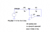
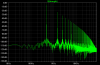
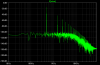
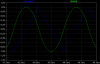
I have bought a 8MHz Oscillator with square wave signals. In order to make my application work, i need the signals in the circuit to be sine. To manage this, I have used a filter found in Horowitz&Hill "Art of electronics", se attached figure. Both the testing on a a breadboard/ simulating in PSpice works out fine, and the signals become nice and smooth sinewaves. Altough the amplitudevoltage are higher than the +5 that comes from the oscillator. I believe this is because of the resonance from the filter.
Because I don\t exactly know what my filtercircuit does to the squaresignals, I would be grateful I would be grateful if anyone could be able to answer the two following questions:
1- What kind of filter have I used for converting the square to sine, and how exactly does it work in order to do so?
2- Are there any better solutions?
Best regards
Tony L
 hm: and with a frequency at 8MHz, according to the LP scaling rules this will give the following values:
") Most hobbyists would not have access to the >50MHz ones that would be required for my suggestion.
Most hobbyists would not have access to the >50MHz ones that would be required for my suggestion.