Continue to Site

Welcome to our site!

Electro Tech is an online community (with over 170,000 members) who enjoy talking about and building electronic circuits, projects and gadgets. To participate you need to register. Registration is free. Click here to register now.

  • Welcome to our site! Electro Tech is an online community (with over 170,000 members) who enjoy talking about and building electronic circuits, projects and gadgets. To participate you need to register. Registration is free. Click here to register now.

Convert a mechanical POT to electronic

Status
Not open for further replies.

TimK

New Member
I have a machine that uses a mechanical Pot and I would like to know if something more reliable can be built. It is in a rather harsh environment and needs to be replaced often.

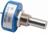
I have attached an image of the pot and below are the specs.

SMT No
Package 7/8in. Round
Number of Turns 1
Technology Conductive plastic
Resistance Value 1kΩ
Resistance Tolerance 20%
Power Rating 1W
Operating Temperature -55 to +125°C
Temperature Coefficient ±600ppm/°C
Rotational Life 5 Million Shaft Revolutions
Linear Or Logarithmic Lin
Effective Travel Nominal 1 turn
Voltage Maximum 500Vdc

And a DataSheet
And a simple drawing of the current set up.

I thought maybe replace the big gear with some kind of coded wheel and a sensor of some kind to read its location. I would need some way to zero it in. Currently I just rotate the small gear on the Pot.

Any Ideas

Thanks
 

Attachments

  • pot.jpg
    pot.jpg
    8.3 KB · Views: 149
  • Pot.pdf
    150.6 KB · Views: 202
  • pot2.pdf
    21.3 KB · Views: 175
The pot is being used as a shaft rotation sensor. First, I notice that the pot shaft is constrained to 1 shaft rotation. Is there a mechanical stop in the pot itself? The way that it is gear-driven suggest that the pot will rotate multiple turns...

There are many different ways to sense shaft rotation, most having direct digital outputs. Since the downstream controller expects an analog signal, are you up to modifiying it?
 
You could use an optical rotary shaft encoder (Google for info). They have a digital output which you would need to convert to the desired signal using a D/A converter or a microprocessor.
 
Last edited:
There is no mechanical stop on the pot.
It would be verry difficult to modify the downstream controller. It is a PLC and we do not have access to the source.
I would have to convert the signal to analog. But I would have no clue how.
As Carl suggested I am going to google optical rotary shaft encoders and see what I can learn.

Thanks
TimK
 
What is this used in? Using a POT like that on a continuously rotating device is right around the area where I'd start calling the designer stupid, especially with a POT rated at 5 million cycles and you saying it's needing to be replaced frequently.
 
Last edited:
I would be interested in knowing the application, what sort of machine this is attached to. I work in industry.

I also have some experience with optical shaft encoders and have an idea for the perfect device here but have to get the part number tomorrow at work.
 
The application is this.

It is used on a payoff machine that supplies wire to a nail machine. The wire is on 2000 pound rolls. The payoff causes the roll of wire to spin at the correct speed at all times.

See photo,

Condensed version of how it works.

The wire is fed through a hole in the vertical arm and into the nail machine which is located to the right of the payoff. When the nail machine starts it pulls on the wire thus pulling the vertical arm forward. When the arm pull forward it causes the payoff to spin faster. When there is slack in the wire the vertical arm is allowed to move back thus slowing the payoff.

The payoff drive speed is variable. The pot in question is connected to a pivot shaft at the bottom of the vertical arm inside the payoff.

Hope this helps

Tim K
 

Attachments

  • payoff.pdf
    6.3 KB · Views: 192
I'm having trouble with your PDF.

But here is a website for shaft encoders that seem pretty rugged.

Dynapar Encoders – Rotary Encoders & Optical Encoders for Motion Control

Most of these encoders are enclosed discs with several (dozens or more) small holes around the circumferance of the disc which are sensed by an slotted IR switch and resolved by a counter circuit. Some use light/dark markings and use reflected beams instead of passing the light through a hole. All of them have a "home" position with a mark or hole (or lack of hole) that is not uniform with the other markings or holes.

As was stated, you have an analog set up currently, and you would need to convert the digital output of the counter to a suitable analog signal. I would imagine that some of the manufacturers of these encoders have ready to use D/A convertors or can recommend a supplier that has compatable equipment. They should be able to guide you in setting this up with minimum effort.

This seems like the way to go for you, this doesn't sound like a hobby project and I know that my company doesn't care too much for McGyver style modifications. A reliable off-shelf product that can be easily repaired or replaced is preferred.

I just found a great tutorial on encoders:
https://www.electro-tech-online.com/custompdfs/2009/10/introduction.pdf
And the root website is a product manufacturer who seems to provide good products with many options and accessory equipment.
 
Last edited:
I got home and was able to view the photo with my acrobat reader, the one at work has some kind of incompatability issue.

I get the gist of your machine...so the payoff system is kind of a tension control for the wire...What sort of motor moves the payoff? Is it a motor with a gearbox? With that large gear driving your smaller gear on the pot, if i don't have it backwards, it would seem the motor turns rather slowly and the pot shaft turns rather fast! No wonder it fails so frequently!

Is there plenty of room inside the machine to mount a "black box" d/a converter and the cabling to your rotation sensor? I would imagine so and that a off-shelf system would be ideal here.
 
It sounds like a closed loop spool tension controller. I think the pot attaches to a "sag" detect lever so it keeps the correct tension by turning the delivery spool faster/slower to keep the arm+pot at the right angle. That's why it was built with a resistive sensor and PLC motor controller.

Maybe the best solution would be to go with a linear type angle sensor, maybe an opto one is available. Or if the detect lever doesn't need to move through too large an angle you could even make one with a opto interruptor mounted near the shaft and an op amp etc to condition the signal. Or even use a inductive proximity sensor that has a linear output, mounted near the arm pivot to convert arm angle into a varying voltage...
 
You could check the voltage the pot puts out for the normal position range of the arm.

Then if the inductive sensor can put out a similar voltage you can just connect it, otherwise you might need a simple opamp circuit to scale the voltage and provide a voltage offset too if needed.
 
Status
Not open for further replies.

Latest threads

New Articles From Microcontroller Tips

Back
Top