Continue to Site

Welcome to our site!

Electro Tech is an online community (with over 170,000 members) who enjoy talking about and building electronic circuits, projects and gadgets. To participate you need to register. Registration is free. Click here to register now.

  • Welcome to our site! Electro Tech is an online community (with over 170,000 members) who enjoy talking about and building electronic circuits, projects and gadgets. To participate you need to register. Registration is free. Click here to register now.

Convert 24 vac to power 2.5 vdc LEDs ?

Status
Not open for further replies.

vinny2cubes

New Member
Sorry if this is a little basic. I want to use some small (3mm) green LEDs to indicate on a laminated aerial photo/panel which irrigation valves are being powered by my irrigation controller. The valves are switched with 24 vac. The LEDs spec says they're 2.2 vdc forward voltage, 2.5 vdc max, 22 mA max current.

I want to connect the LED to each valve terminal on the controller to indicate that the valve is powered. The 24vac LED's I found online are too large for my map/display board.

Would this be as easy as soldering a resister and diode to the positive lead?

I think I'd need a 990 ohm resister to drop it to 2.5 vdc... not sure how about converting to ac...

Any help would be appreciated.

Thanks.
 
To power your LED from 24Vac, use a series resistor, chosen to limit the current to about 20mA, and a silicon diode, like a 1n4148 or 1n400x (1<=x<=7) wired cathode to LED's anode and anode to LED's cathode. The resistor limits the current, the diode prevents reverse voltage from appearing across the LED.

WAG for the resistor value: 1.1K 1W
 
The LED is already a diode, so no conversion is necessary, as long as reverse breakdown voltage isn't violated. Just use a suitable sereis resistor to limit the current to 22mA.
 
Last edited:
I thought about it some more, and here are three different ways to drive an LED from 24Vac:
 

Attachments

  • 3WayLED.jpg
    3WayLED.jpg
    323 KB · Views: 3,655
The LED is already a diode, so no conversion is necessary, as long as reverse breakdown voltage isn't violated. Just use a suitable sereis resistor to limit the current to 22mA.

hi,
Due to their construction LED's have a 'low' reverse breakdown voltage, in the order of 5V, so with a 24Vac [33Vpk] a antiparallel diode is required.
 
After thinking about it some more, I modified the three ways as shown below. The problem the additional component solve is to limit the current through the LED as the valve is switched on and off. By the time you add the series resistor to the Capacitor circuit, and considering that a non-polarized capacitor that big is hard to find and expensive, there is no advantage to it. I would use the middle circuit. The added 10nF capacitor protects the LED against the spike when the valve turns off.
 

Attachments

  • 3WayLEDa.jpg
    3WayLEDa.jpg
    322.7 KB · Views: 1,779
Last edited:
Mike,

You said you would use the middle circuit... but you show 4 circuits. Which one would be the middle circuit???

Thanks

Vinny
 
The left "circuit" is just the test stimulus for the other three in the simulation :D
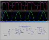
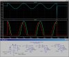
, so there are only three LED circuits. The middle one ("series") has the rectifier diode in-series with and pointing the same direction as the LED. That reduces the current (and the heat dissipation) in the current-limiting resistor. The reverse-voltage appears across the diode; not the LED.

The stuff to the left is the source of the 24Vac, the inductor simulates the coil of your sprinkler valve. The switch simulates the TRiac inside your sprinkler timer. The signal called S24 is what you will be connecting your LED indicator to...
 
Last edited:
Mike,

Duh... I looked at it after posting and finally figured out that was the source of the 24 vac. Sorry. So the series circuit looks simple enough. I made a google search for the 1N148 diode but didn't find anything. Where would I find this? What would you suggest as a good source and what would be the best of each suggested component to buy for this little project?

I really appreciate your info and help. Made my day so much simpler!

Vinny
 
That should be 1n4148!

1n914, 1n4148, 1n4000-1n4007 would work (basically, any Silicon diode/rectifier); some of these might even be at RatShack.
 
Last edited:
I'm sorry to be a pain, but I'm a total newb when it comes to finding these parts. Could you tell me the capacitor specs for C3 I should buy? Is it 10 nF (I'm not sure I see such a thing in the digikey catalog....)
 
10nF=0.01uF=10000pF="103" marked on it. Not critical. Do you have any discarded electronics junk (like an analog-only TV set:D, old modem, old computer) lying around. You could find all the parts you need in those...
That is why I never throw anything electronic out. I recycle it for parts.
 
Looking through a catalog like Digikey gives me a headache... there are so many types that don't really narrow down the choices (seems like a million versions of everything). I look for capacitors and see so many different types, but don't know which one to pick. Axial or Disk, ceramic or electrolyte, so many choices, and none seem to be .01 uf or 10,000 pf. I'd go scavenge junk stuff like you suggest, but I need 24 of each. Although it's a lot to ask, which would you choose?

Thank you again for your patience with my absolute neophyte questions.

Vinny
 
Try DigiKey 1460PH-ND
 
In addition to the green LED, I was wondering how hard it would be to have red LED's to indicate that the valve was off (unpowered)? I found a circuit in the Radio Shack green book (voltage monitor page 124) that illustrated something like that, but don't know how it would work with 24 vac in my situation... seems like it would get complicated and $$$ for 24 valves.

Thanks for all the help
 
Do you want the red led to be ON when the valve is OFF, and the green led when that same valve is ON? Have you seen the Red/Green Bicolor LED that are inside a single package?
 
Mike,

Wow, that would be great... one LED with both colors, green for 24 vac, and red when valve is unpowered. Didn't know they had multple colors in one LED. How would that work in my project? The circuit I was looking at used an 741 op-amp to detect voltage.

Thanks

Vinny
 
Status
Not open for further replies.

Latest threads

New Articles From Microcontroller Tips

Back
Top