Continue to Site

Welcome to our site!

Electro Tech is an online community (with over 170,000 members) who enjoy talking about and building electronic circuits, projects and gadgets. To participate you need to register. Registration is free. Click here to register now.

  • Welcome to our site! Electro Tech is an online community (with over 170,000 members) who enjoy talking about and building electronic circuits, projects and gadgets. To participate you need to register. Registration is free. Click here to register now.

Controlling the brightness of RGB LED

Status
Not open for further replies.

MisterG65

New Member
Good Morning
I'm trying to build a circuit to show students primary and secondary colours using an RGB LED (common cathode). Using switches gives an approximation but the colours are a bit off - eg yellow is more a lime green.

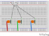
I'm trying to find suitable resistors to make it more convincing, but here I've encountered a problem. When changing the brightness of the Red component it goes from red to off and back to red again as I turn the pot (10k).

I'm attaching the circuit layout to see if this is basically wrong (I haven't really studied electronics for 30 years!)

Thanks in advance
 

Attachments

  • PotLED.png
    PotLED.png
    119 KB · Views: 165
The most likely reason the red LED goes off again is because you are not limiting the current and the die overheats to the point that the light output drops off so much that you can't see it. Either that or you have burned one end o f the resistive element in the pot. To guard against overheating and possibly ruining the LEDs and burning your pots, you really should have a fixed resistor in series with each LED. Based on the apparent size of the LED you should keep the current to a maximum of 20 ma.
 
The maximum allowed current for the LED is probably 30mA for each color. Without limiting the current then it might have been hundreds or thousands of mA. I bet the LED and the pot are burned out.
The power supply voltage is not mentioned. With a 9V battery and a current of 20mA in the 1.8V red part of the LED then a resistance of (9V - 1.8V)/20mA= 360 ohms or 330 ohms should be in series with the pot. The total resistance of 10,360 ohms will cause dimming but the LED will still be very visible.

EDIT: The green part and our vision are more sensitive than the red part so turn down the green level instead of overdriving the red.
 
The red LED isn't burnt out AFAIK. The red colour appears at the extremes of the pot's rotation (ie 0Ω and 10kΩ). The green overrides it in between (blue was disconnected).
Sorry I didn't indicate the battery used - I've connected 2 AA cells, with a nominal total of 3V. My original circuit (attached) would take 9V but the colour balance was even worse.
 

Attachments

  • RGB_Button.png
    RGB_Button.png
    176.2 KB · Views: 143
Your color balance is bad because the pots are not connected properly. It looks like you used pushbuttons instead of 10k pots. When a 10k pot is connected properly as a rheostat then it adjusts from 0 ohms smoothly to 10 thousand ohms. Then the brightness of the LED is bright when it has the 330 ohm resistor and is dim when it has 10,330 ohms.
3V from 2 alkaline cells is only when they are brand new. When they are used only a little then the blue and maybe the green will not light because they need about 3.2V.
 
Your color balance is bad because the pots are not connected properly. It looks like you used pushbuttons instead of 10k pots.

Which of my diagrams are you looking at? The image at the top of the thread it the current set up, with the pots. The second one does have pushbuttons. This is just to show you what I am trying to work towards. In the "pushbutton" circuit the current limiting resistors are all the same. I'm trying to use the potentiometer circuit to fine tune this, using different resistors to alter the brightnesses of the three components. I am open to suggestions!
 
With a 10k pot in series with a 330 ohm resistor and in series with an LED then you can adjust its brightness without destroying anything.
 
I happen to have some of those LEDs, and I damaged one so it still seems to work but not properly (so if you have a spare, use it because yours is probably damaged - as is warned above). I found (as also mentioned above) that a nominal 3v was too low, so I opted for a PP3 (nominal 9v). For the red LED, you'll need a 1M pot in series with a 10K resistor, for the green and blue LEDs, you'll need a 5M pot in series with a 100K resistor for each, and even then the results are not perfect, because both the latter still glow at 1.7μA. I think the manufacturer could have matched the red to the others better. I ended up using PWM instead, but that might be overkill for you. You might find it easier to get the resistor values right and then use a BCD switch to select the 7 colours (+ none on=8). Do you teach science?
 
Would 3 adjustable constant current sources built around LM317 voltage regulators be easier?
 
I happen to have some of those LEDs, and I damaged one so it still seems to work but not properly (so if you have a spare, use it because yours is probably damaged - as is warned above).
I bought 50 as a job lot ... I want to make a load eventually!

I found (as also mentioned above) that a nominal 3v was too low, so I opted for a PP3 (nominal 9v). For the red LED, you'll need a 1M pot in series with a 10K resistor, for the green and blue LEDs, you'll need a 5M pot in series with a 100K resistor for each, and even then the results are not perfect, because both the latter still glow at 1.7μA.
Thanks - it'll save me a lot of messing about
I ended up using PWM instead, but that might be overkill for you.
My original idea was to use an ATTiny, but it was going to run short of pins

use a BCD switch to select the 7 colours
Not met one of these before. I really wanted to keep it simple, showing the combinations of RGB (and possibly fudge this if going down the arduino route!
Do you teach science?
Yup. Since 1988! Mainly Chemistry, but also have some input in Physics. This is more a hands-on thing for our younger students (age11/12)
 
kwixyx1415257736491.jpg

There are many versions of this. This is a strip of RGB LEDs. You can set the color you want.
I think you can get the LEDs in singles.
No resistors. lol
 
You could use the tiny and shift registers to get more pins..........
 
ronsimpson Bit of an overkill, but thanks. I want the kids to be able to push eg the red button and the blue button to see cyan, rather than the cyan button to get cyan ;)

Little Ghostman I could, but I'd have to learn how to use them! Also, it would be overly complicating things.

BTW The usual method of torches and coloured filters also gives lousy results!
 
Wow 29 years - you're a glutton for punishment!

The other problem I had was that it is possible to see the individual LEDs within the package so I added some diffusion (some tracing paper) over it. Sort of worked.
 
Last edited:
I saw a hack where a ping pong ball had a hole drilled in it and was used as a diffuser
Thats exactly how I made our outside christmas lights :D
 
Status
Not open for further replies.

Latest threads

New Articles From Microcontroller Tips

Back
Top