Continue to Site

Welcome to our site!

Electro Tech is an online community (with over 170,000 members) who enjoy talking about and building electronic circuits, projects and gadgets. To participate you need to register. Registration is free. Click here to register now.

  • Welcome to our site! Electro Tech is an online community (with over 170,000 members) who enjoy talking about and building electronic circuits, projects and gadgets. To participate you need to register. Registration is free. Click here to register now.

Control of Vout (HV Power Supply)

Status
Not open for further replies.

pikstart

Member
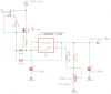
The attached is a high voltage (up to 250Volt/0,4A) power supply.

The Vout is controlled by the potensiometer at 1V/1Kohm.

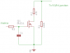
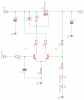
I'd like to control this voltage by a Microcontroller and replace the potensiometer by an electronic variable resistor of some kind.

Have tried different ideas, like a JFET, MOSFET, BJT but all suffer in one way or another of Temp drift or narrow band of control.

Any idea welcome.
John
 

Attachments

  • High voltage power supply.png
    High voltage power supply.png
    8.8 KB · Views: 144
The limiting factor is that, with most digital pots, the highest voltage that can appear on any of it's terminals is less than or equal to the pots supply voltage. Typically 5 volts.
 
The problem is that the voltage at the top of the pot reaches almost all the way to 250V. Watch the power dissipation in any variable resistor you put there...
 
Yes, you are right. But there are not many LDR for up to 250 or better 500Volts. And Power dissipation is low for the application.

Back to square 1.

Ioannis
 
Hmm, since the LDR and light source are out of the loop, a lamp would probably not be very stable. Maybe a white LED is more appropriate.

Also the LDR should not be temp dependent. Datasheets are not rich on these info.

Ioannis
 
Your computer can talk "servo" and that will turn a Pot. Depending in the servo software you will get 256 or 1024 resolution.
upload_2018-4-20_13-49-55.jpeg
upload_2018-4-20_13-47-15.jpeg
 

Attachments

  • upload_2018-4-20_13-49-41.jpeg
    upload_2018-4-20_13-49-41.jpeg
    27.1 KB · Views: 100
You can drive a high voltage MOSFET in series with a resistor with pulse width modulation to adjust the "average" resistance. That would mean that you would have to filter the feedback signal before letting it into the regulator.

In the case of a single resistor and a MOSFET the average resistance would be R' = R/(duty cycle).
At 0% duty cycle average resistance is infinite (so you might want to shunt the MOSFET with a resistor.
At 100% duty cycle the average resistance is equal to the value of the resistor.
 
Thanks Dick.

I tried that and although it seems so natural, it does not work. Or at least I was not able to make it work.
 
I think you could ditch R4 and regulate voltage directly at the SET pin. Use a pullup to the input pin (with some protection diodes) and a transistor to pull down, controlled by an opamp with some reference voltage source.
 
What is the total output voltage adjustment range you need? This is not stated in post #1.

ak
 
Thank you all for the replies.

AnalogKid: the output range is from 50-200 volts

kubeek: The R3 and R4 are needed both. They form a current divider keeping 10μΑ for the set pin and 1mA the min current for the LT3080 to work properly. Both are then connected to pot regulating output at 1V/1K.

Dick: I used the circuit attached. Unfortuately, resistors does not seem to be simulated well with PWM and duty-cycles. The Enhancement Mosfet is not the BUZ11 but a IRF740 High voltage one. Just did not find it in lib.

Ioannis
 

Attachments

  • Mosfet-1.png
    Mosfet-1.png
    2.9 KB · Views: 99
Interesting....The idea is to switch the transistor on and off with PWM, then filter the pulse stream from the divider. The circuit you show should still work but it would pass from full off to full on (practically speaking/writing) over a very narrow range of PWM values. I was thinking of a circuit more like the one below. I should have sketched it out for you in the first place.

Notice that Cnew will affect the regulator's step response -not the best topography for this technique, it would not have an issue with step response if on the reference than on the feedback.

upload_2018-4-30_19-19-24.png
 
Well, including a capacitor does help indeed.

But,
1. The range of control is from 53 to 58% duty
2. Temp of the Mosfet shifts very much the setting point. No regulation at all!

So, even accepting the small range of control, the temp drift is too much.

Thanks anyway.

I am dropping the idea of using the excellent circuit because have not found a way to control it by a PWM signal.

These days I was experimenting with another idea from the Microchip forum Member Paul. He suggested to use a differential transistor circuit driving a PNP or Pchannel Mosfet transistor.

The one transistor of the differential pair is sampling the Vout and the other is driven by the PWM signal. Looks promissing but has a lot of issues to take care, strating with 5-8 volts drop connecting the load to the output.

I attach the temp circuit.
Ioannis
 

Attachments

  • HVPS.png
    HVPS.png
    6.7 KB · Views: 113
That circuit makes a lot of sense, except that D1 and D2 seem to throw off the temperature stability. Please let us know how well this circuit works once you have ironed out the wrinkles.
 
Status
Not open for further replies.

Latest threads

New Articles From Microcontroller Tips

Back
Top