Continue to Site

Welcome to our site!

Electro Tech is an online community (with over 170,000 members) who enjoy talking about and building electronic circuits, projects and gadgets. To participate you need to register. Registration is free. Click here to register now.

  • Welcome to our site! Electro Tech is an online community (with over 170,000 members) who enjoy talking about and building electronic circuits, projects and gadgets. To participate you need to register. Registration is free. Click here to register now.

control circuit(toggle latch). need review

Status
Not open for further replies.

naren

New Member
pls review the circuit mention below. Its a simple toggle switch to switch ON the relay. If the computer is not available, the manual bypass button will be used.

regards,
naren
 

Attachments

  • CIRCUIT_130.jpg
    CIRCUIT_130.jpg
    34.7 KB · Views: 1,181
  • CIRCUIT_139.jpg
    CIRCUIT_139.jpg
    34.7 KB · Views: 1,205
Well i think your use of the opto isolators (4N25's) is a good idea since it will be connected to a computer. But is it really necessary to have two ? The 4N25 driving the relay should give the circuit sufficient isolation.

Also if you are using this circuit with your parallel port , you can get opto isolators (or couplers) with up to 8 in a single package. This will save you some board real-estate and simplify the layout abit.

Can you tell us what this circuit will be used for and what control features you are considering in the design ? It may help in the assessment.
 
hi,

thank you for evaluating my circuit. The circuit will be used to control heavy duty(250VAC, 10A) relays. The relay are connected to a solenoid valve. The reason is, i would like to control what types of water + solvent will be used for the particular substrate. This gives me the control to ensure no fatigue is observed on the substrate due to manual valve failure. majority of the time we forgot to turn the valve for the correct substrate.

I want the control feature to be robust and reliable as in 365days non-stop performance.

thanks,
naren
 
As you prolly already know, the circuit itself without the mechanical relays and solenoids will be quite reliable, its the moving mechanical parts you have to worry most about. So you could say the circuit is only as good as the parts it is controlling.

Some questions:

How many relays-solenoids will the circuit be controlling ?
What is the purpose of the 4017 multiplexor ?
and will there be two or more relays on (energized) at the same time ?

I used a similar set-up to drive relays using a 74LS154 multiplexor controlled via a connection to the parallel port of my computer. It could drive up to 16 relays in any combination and at different times under software control.


Net
 
Some questions:
How many relays-solenoids will the circuit be controlling ?
ans: 1 relay-solenoid for each circuit

What is the purpose of the 4017 multiplexor ?
ans: its the only circuit i am well versed in

and will there be two or more relays on (energized) at the same time ?
ans : yes

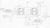
pls refer below for a detail explanation


the reason i am using 4017 is its simplicity(i.e. toggle ON and toggle OFF). So, one of the led will switch ON the relay and if i press toggle it will switch off and light the other led.
This is the only ic i am well versed in. The circuit you have seen above, they will be a replica of 7 more-each for one computer port input and separate relay drive. (total 8 circuit)

This is made so that they have individual input and output control. If one of the circuits burn down, i'll probably swap it with a spare without shutting down the other circuit.

For 4017 input voltage would not be a constrain(3 - 12 VDC). If i can use a 7805 to limit the voltage to logic 5VDC for 74LS154. They are 2 reasons i am not using this :-

a) I am not well versed on how to build the complete 74LS154 circuit(like the control i need above). I only know about this chip when you have pointed it out to me. (Thanks)

b) If lets say i am using a 5VDC relay, and it burns out. At hand i have another relay with the same specification but it is a 9VDC relay, till the parts arrive i could temporary used this in the circuit and all i have to do is increase the input voltage and add voltage resistor to the other 5VDC relay to protect them. Its resourceful.

I am building the circuit using ic sockets so any parts on the board can be changed just like inserting an ic.

regards,
naren
 
Status
Not open for further replies.

Latest threads

New Articles From Microcontroller Tips

Back
Top