Continue to Site

Welcome to our site!

Electro Tech is an online community (with over 170,000 members) who enjoy talking about and building electronic circuits, projects and gadgets. To participate you need to register. Registration is free. Click here to register now.

  • Welcome to our site! Electro Tech is an online community (with over 170,000 members) who enjoy talking about and building electronic circuits, projects and gadgets. To participate you need to register. Registration is free. Click here to register now.

Control a line of LEDs from one pin.

Status
Not open for further replies.

Blueprint

New Member
How would you control a row of LEDs using one output pin? I've seen this done (and have even bought/built the Velleman kit **broken link removed** (KIT: MK124)) which is controlled by ONE PIC.

I want to make a 6x3 matric of LEDs (for the newer version of my binary clock) controlled by one PIC.

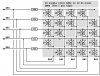
The LED matrix will look like:

Code:
[][] [][] [][]
[][] [][] [][]
[][] [][] [][]

[] = LED

Each set of six LEDs will be controlled by one pin. Is this possible? I'm sure it is!
 
Here is how I'd do it. I'd multiplex a row of LEDs a time. The eye is not fast enough to see the LEDs alternately being turned ON. Using ultra bright LEDs and with a lower LED current, you might get away not using transistors.
 

Attachments

  • led_420.gif
    led_420.gif
    7.2 KB · Views: 1,684
motion said:
Here is how I'd do it. I'd multiplex a row of LEDs a time. The eye is not fast enough to see the LEDs alternately being turned ON.
You can use 4017 IC to save couple of I/Os on that transistors. 4017 allows you to controll 10 transistors with only 1 pin (+maybe RST to keep track on position).
 
If you review the Velleman kit, it does away with transistors and drives the LED directly from the PIC.
 
Use an multiplexer IC to do this.

Microchip has some I2C and SPI multiplexers up to 16 outouts.The SPI version is prety fast (you can order free smaples of them)
 
Why not to use Charlieplexing. For example you can controll 12 LEDs from just 4 I/Os...
 

Attachments

  • cherlieplexing.gif
    cherlieplexing.gif
    4.4 KB · Views: 1,613
  • led_91029a.pdf
    69.1 KB · Views: 394
Blueprint said:
Each set of six LEDs will be controlled by one pin. Is this possible? I'm sure it is!

Your question is VERY misleading, hence the rather confusing answers!.

Presumably what you're asking is how the Velleman kit actually works?, motion answered that early in the thread!, the LED's are multiplexed across a number of I/O pins. As it's a 6x5 matrix, it requires 11 I/O pins to drive it.

If you check my seven segment LED tutorial, I use exactly the same technique to feed two seven segment displays off only 8 I/O pins.

As the Velleman kit drives the LED's directly from the PIC, it severely limits the available brightness - a matrix of 6x5 LED's restricts the maximum average LED current to only 5mA - with a maximum of 30mA per I/O pin.
 
Charlieplexing is a viable option but it'll require 5 pins -- this is sometimes referred to as the N*(N-1) scheme where 4-pins will yield 12 distinct circuits, 5-pins will yield 20, 6-pins will yield 30, etc.... Charlieplexing takes advantage of the tri-state or input-state of an I/O pin, when the pin will neither sink nor source current...

The "5-Pin 20-LED" example circuit below is the same circuit Jay described but drawn a little differently (and for 5 pins)

The "7-Segment" circuit shows 8-pins driving four 7-segment LEDs but if you look closely at the little inset drawing you'll see this circuit will actually support eight (8) 7-segment displays with 8-pins...

Search the "Digital I/O" section of Forum.Microchip for "Charlieplexing" discussions and sample interrupt code for driving the LEDs...

Regards, Mike
 

Attachments

  • charlieplexed_20_leds.jpg
    charlieplexed_20_leds.jpg
    75.6 KB · Views: 1,605
  • charlieplexed_8-pin_4-digit_cc.jpg
    charlieplexed_8-pin_4-digit_cc.jpg
    65.7 KB · Views: 1,568
More Charlieplexing examples for 7-Segment displays, for those who may be interested...

These drawings are quite different but will hopefully be a little easier for analyzing actual circuit paths and for visualizing the "float bit" concept required for Charlieplexing...

Have fun... Regards, Mike
 

Attachments

  • charlieplexed_9-pin_8-digit_cc_2n2907_191.jpg
    charlieplexed_9-pin_8-digit_cc_2n2907_191.jpg
    123.2 KB · Views: 1,486
  • charlieplexed_8-pin_8-digit_cc_2n2907.jpg
    charlieplexed_8-pin_8-digit_cc_2n2907.jpg
    116.7 KB · Views: 1,565
Ok... well i've decided to simply show 12 LEDs for now (hours and minutes in binary). It'll look like the following:

Code:
       [][] [][]
       [][] [][]
Hours> [][] [][] <Minutes

 +-Hours-+  +-Min's-+
 |[]11[]8|  |[]5 []2|
 |[]10[]7|  |[]4 []1|
 |[]9 []6|  |[]3 []0|
 +-------+  +-------+

[]=LED

However, I read through the Charlieplexing pdf file, and it seems to state that only one LED may be on at a time? I may need more than one LED on at a time :shock: :?: :?:

For example, the time 23:55 in binary must look like:

010111 : 110111

Where the 1's are LEDs that are ON, and the 0's are LEDs that are off (obviously).

Any "bright", pardon the pun, ideas?

EDIT:

Nigel what's confusing about "Each set of six LEDs will be controlled by one pin. Is this possible? I'm sure it is!"? I'll draw a diagram again, but with the LEDs in a different layout:

Code:
-+
 |-----+
P|---+ +--[][][][][][] <<Hours
1|-  +----[][][][][][] <<Minutes
6|-
F|-
8|-
4|-    
A|-
 |-
-+


[] = LED

Also, the Velleman kit uses 7x5 LEDs but they all manage to stay very bright, well bright enough for the device I'm making.

Anyway I'm going to keep playing around, even if I need to use more I/O ports for the decide it's ok, however I need to reserve 3 for switches to set/edit/show the clock. That leaves 10 pins for this device.
 
However, I read through the Charlieplexing pdf file, and it seems to state that only one LED may be on at a time? I may need more than one LED on at a time

To the software only one LED is ON at a time but to the person viewing the clock, any number of the LEDs will appear to be ON. As I said, the eye is not fast enough to tell the difference. Not only will this limit the brightness the LED can shine but the software has to be more sophisticated.

This is specially so if you have to add the timing software for the clock. The delay routines you are using just can't cut it. You may have to rely on TMR0 the get the right amount of delay regardless of how complicated the display part of your program becomes.
 
I'm using a timing crystal (32.768kHz) to keep count of the passing seconds... does this mean I can't use, say, a 4Mhz crystal in the circuit to keep the fast switching of the LED's ongoing?
 
Any "bright", pardon the pun, ideas?

You have to breakdown the program in parts. I would suggest to break down the program into three parts:

1. clock delay part - This part generates the precise timing needed to keep correct time over a long period. You don't want your clock to gain/lose a few seconds in a day.

2. Clock LED formatter - Once you get the timing right, you need to generate the pattern of LED ONs anf OFFs. You can save an image of the LED display stored in memory first. For example, you store the pattern 010111 : 110111 in the PIC file register first.

3. LED Multiplexing part - Regardless of which method of LED multiplexing you decide, you can put it in a separate part so it does not affect the other two parts. In this part, the pattern of LED ONs and OFFs in part 2 is now sequentially but rapidly written to the output port so in realtime it appears to be lit simultaneously.
 
Blueprint said:
I'm using a timing crystal (32.768kHz) to keep count of the passing seconds... does this mean I can't use, say, a 4Mhz crystal in the circuit to keep the fast switching of the LED's ongoing?

A 4Mhz crystal will not divide down to a precise multiple of one second. However, there are techniques to closely approximate one second so that it does not lose/gain seconds over several days. A simpler way is to use a 4.096Mhz crystal.

An advantage of using the 32768 crystal is it does not use up too much power. You can power the PIC from batteries when line power is OFF. Just turn OFF the LEDs to conserve power during blackouts.
 
motion said:
If you review the Velleman kit, it does away with transistors and drives the LED directly from the PIC.
true .. i have done it with pwm , but i was carefull not to turn it up all the way...
 
williB said:
motion said:
If you review the Velleman kit, it does away with transistors and drives the LED directly from the PIC.
true .. i have done it with pwm , but i was carefull not to turn it up all the way...

Nothing to worry. There are limiting resistors on the other side of the matrix.
 
Status
Not open for further replies.

Latest threads

New Articles From Microcontroller Tips

Back
Top