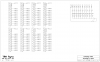
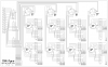
The attached schematic is for a splitter box and continuity check to be used on an existing fireworks firing panel purchased from ODA. The firing panel uses DB25 connectors with the hots in pairs for 10 cues and the remaining 5 wires used for grounds. I paired the wires up before the rotary switch so I would only have to switch 11 wires which makes the rotary switch attainable. The schematic starts at the splitter box input and does not include the firing panel schematic.
1 & 14 - Cue 1
2 & 15 - Cue 2 and so on
11, 12, 13, 24, 25 are grounds
I am a little unclear on the continuity circuit as far as resistor and diode placement. I am trying to isolate the continuity circuits from firing voltage by using the diodes. Please let me know if there are errors or if I missed anything as electrical design is not in my comfort zone. You may have to transfer the files in order to view them properly. If there is a better format for posting schematics let me know; I am using ExpressSCH.
Thanks