Continue to Site

Welcome to our site!

Electro Tech is an online community (with over 170,000 members) who enjoy talking about and building electronic circuits, projects and gadgets. To participate you need to register. Registration is free. Click here to register now.

  • Welcome to our site! Electro Tech is an online community (with over 170,000 members) who enjoy talking about and building electronic circuits, projects and gadgets. To participate you need to register. Registration is free. Click here to register now.

Constant Current Source

Status
Not open for further replies.
I would like to make a CCS (Constant Current Source) for testing loudspeakers.
I've used the constant voltage and voltage divider methods but I don't know what the requirements are for a CCS for this application.
Can someone give me some info or maybe a pointer to a schematic?
 
pandaemonium said:
I would like to make a CCS (Constant Current Source) for testing loudspeakers.
I've used the constant voltage and voltage divider methods but I don't know what the requirements are for a CCS for this application.
Can someone give me some info or maybe a pointer to a schematic?

Perhaps you should explain more what you are trying to do?, it doesn't make much sense to me?.
 
I want to measure the Thiele/Small (and other) parameters of speakers. There will be a sine wave generator at the input of the CCS and the speaker at the output of the CCS. The voltage of the CCS will change according to changes in the impedance of the speaker, I will measure this at various stages to calculate the speaker parameters.
 
pandaemonium said:
I want to measure the Thiele/Small (and other) parameters of speakers. There will be a sine wave generator at the input of the CCS and the speaker at the output of the CCS. The voltage of the CCS will change according to changes in the impedance of the speaker, I will measure this at various stages to calculate the speaker parameters.

A constant current source is generally DC, but a simple way to do it for this is to use a high power (and thus high voltage!) amplifier to drive it. You can then feed the speaker through a highish value resistor, and as this effectively swamps the impedance of the speaker it produces a fairly good constant current.

This is a VERY! old technique for giving a constant current!, probably older than Audioguru? :twisted:
 
This circuit puts 2mA DC into the speaker, but since the level is low, it should not affect the measurment. The AC component can be 2 ma peak max.
 

Attachments

  • spkrtst.jpg
    spkrtst.jpg
    41 KB · Views: 892
I just feed the speaker through a 100 ohm resistor directly from the output of my sinewave generator.
 
An old thread (very old), but I have a similar end goal - toward learning about musical instrument pickups, I want to be able to plot their frequency responses(then I can change things & see what the outcome is). I'd like to do this via a transmitter coil.....basically it entails sending a sine wave frequency sweep into a transmitter coil - which in turn is located close to the pickup .....& plotting the resulting pickup frequency response - but to do this, I need to ensure that the the current through a transmitter coil remains constant no matter what the frequency......

The method is spoken of here...

BuildYourGuitar.com :: The Secrets of Electric Guitar Pickups the part headed "Measuring Frequency Response" (about 2/3rds of the way down the very long page)

any input warmly received!
 
Many years ago I souped up the cassette tape recorder in my car radio. I used a high output impedance constant current source to drive the inductive recording head, similar to what you are doing. It sounded excellent.
But today I can't remember the circuit.
 
It sounds like a great project, and pretty original too! :)

You will have to make sure the transmitting coil is an air coil with no magnetic material, so you won't get losses from the transmitting coil.

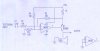
Then you drive the coil with a LM1875 or other high freq very low distortion amp chip. And since that amp chip is basically an op-amp with + and - inputs, you can make it closed loop.

So you have a fixed amplitude input sinewave, easy enough, into the amp chip + input, and a non-inductive current sense resistor in series with the transmitting coil (on the ground side).

Then the signal from the current sense resistor is fed back into the - input of the amp chip so it regulates instananeous coil current to match the incoming sine wave.

It should work very well, the result willl be a fixed sine current ay any frequency. All it needs really is a signal generator and amp chip and the coil (and a few discretes).

It's a cool project, if you wanted to start your own thread and document your build I will subscribe to it. :)
 
Sorry for the delay....got waylaid!

That LM1875 looks ideal (wire it up just like an non inverting opamp as you say).... I was wondering if anyone knew of other similar chips but a bit smaller (I'm looking for something SOIC08...just about 1W)

There seems to be a plethora of audio power amps with external gain setting resistors but wired as an inverting config ......so just wondering if they could be rejigged to be non-inverting.

For example...

https://www.electro-tech-online.com/custompdfs/2011/07/121_SGM4871.pdf

If you look at their IC 'internals' diagram on page 4.

What I was thinking was.....

1. Put the signal into the +ve pin (vs the -ve pin as they have it)
2. 'Bias up' the +ve pin with a resistor to the SVR/Bypass (pin 2).

I could then place a small value resistor in the load path (ground side) & 'feedback' the junction signal into the -ve pin ....voila constant current?!!!

Bit worried about the likely impact on phase margin and potential for oscillations though.
 
Last edited:
You can easily make the IC amplifier inverting or non-inverting.
It has a constant voltage output not a constant current output because its output impedance is extremely low.
 
Last edited:
Status
Not open for further replies.

Latest threads

New Articles From Microcontroller Tips

Back
Top