mpegjohn
New Member
Hi,
I am designing an inductance bridge for iron cored inductors of around 10H 100mA
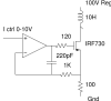
I need a constant DC current of upto 100mA, to do this I have a stabilized 100V PSU, that feeds the top of the inductor.
The circuit is a standard current sink using a high voltage Mosfet.
Looking at the drain of the Mosfet, I can see quite large voltage spikes, that seem random, but quite large.
If I replace the inductor with a resistor, all is calm and there is no noise to speak of.
So it does seem to be the fact that this is an inductor. I have tried putting the inductor in a diecast box, to see if it was some form of pick up, but this made no difference.
Any ideas?
John
I am designing an inductance bridge for iron cored inductors of around 10H 100mA
I need a constant DC current of upto 100mA, to do this I have a stabilized 100V PSU, that feeds the top of the inductor.
The circuit is a standard current sink using a high voltage Mosfet.
Looking at the drain of the Mosfet, I can see quite large voltage spikes, that seem random, but quite large.
If I replace the inductor with a resistor, all is calm and there is no noise to speak of.
So it does seem to be the fact that this is an inductor. I have tried putting the inductor in a diecast box, to see if it was some form of pick up, but this made no difference.
Any ideas?
John

")
 , I took the PMOSFET number from post #5. I didn't notice that you had used the IRF730, which will be fine on secondary break-down grounds, as you no doubt already knew.