Continue to Site

Welcome to our site!

Electro Tech is an online community (with over 170,000 members) who enjoy talking about and building electronic circuits, projects and gadgets. To participate you need to register. Registration is free. Click here to register now.

  • Welcome to our site! Electro Tech is an online community (with over 170,000 members) who enjoy talking about and building electronic circuits, projects and gadgets. To participate you need to register. Registration is free. Click here to register now.

Connecting thermocouples and whatnot!

Status
Not open for further replies.

Jacko0752

New Member
Hey guys and girls - I recently bought a thermocouple and a temperature display from China. I am planning to use this in my smelting forge - now I’m stuck looking at a diagram which means as much to me as a Sunday school hat to a pig...
would anyone be able to help to explain where do I connect the coupler and how to connect the power to the temperature controller?
Thank you all
 

Attachments

  • 1D99D6F7-56D2-40EE-9F57-FECF52C0878F.jpeg
    1D99D6F7-56D2-40EE-9F57-FECF52C0878F.jpeg
    1.5 MB · Views: 156
  • 6BC68D2A-8506-4374-8E86-301DBEA9CB93.jpeg
    6BC68D2A-8506-4374-8E86-301DBEA9CB93.jpeg
    1.5 MB · Views: 144
  • B75CD3AA-74BC-4C39-B39E-592926A41E14.jpeg
    B75CD3AA-74BC-4C39-B39E-592926A41E14.jpeg
    1.3 MB · Views: 141
Welcome to ETO.

Try this:

Connect the mains power supply to terminals 1 and 2

Connect the thermocouple to terminals 9 and 10.
Best guess, connect the red end to the TC to terminal 10 and the blue end to terminal 9.

Without any details of your power controller I hesitate to suggest how to connect to it.

To check that the connections are ok so far, apply power and look at the displayed temperature, it should show around ambient temperature.

JimB
 
The color code for the thermocouple. Contrary to normal convention, the red conductor is negative and the yellow positive.

tc color code.jpg


Per the label, the negative conductor of the thermocouple goes to terminal 9, the positive to 10, so red to 9, yellow to 10.

tc-1.jpg


The terminal numbers are marked on the back - just match them to the label.

tc-2.jpg
 
Thermocouples have types and colors. e.g. J,K, R, S, T where K is the most common. The outer jacket is yellow for K.

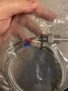
Probes come in grounded and ungrounded configurations. Wires can have a junction made on them. i won;t talk about making a junction.

With a thermocouple meter that can read room temperature, some can't, any wire across the thermocouple inputs will read room temperature.

K or Chromel-Alumel. Red is the negative lead. I forget the other color. Lots of info on www.omega.com Red is universally negative.

Another word: Extension wire

Extension wire for K thermocouples will look like copper wire. it's not. It's also NOT to be used as the thermocouple. It's only supposed to be used to extend the wire to the thermocouple.

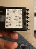
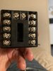
A K thermocouple connector will have a yellow housing and come in at least two sizes. These connectors are designed to be isothermal or to keep both connections at the same temperature and have the electrical properties only of a real thermocouple at least at room temperature.

You select a thermocouple type by it's temperature range and environment it will be in.
"T" is good for cryogenic and room temperature. "C" for very high temperatures like for melting copper.

When we talk about probes, we can also talk about wells. If you wanted say a C thermocuple probe in a tantalum well. This makes the well replaceable.

The right type thermocouple for the instrument connected backwards means when you heat the TC, the temperature goes down and not up.
 
Last edited:
Status
Not open for further replies.

Latest threads

New Articles From Microcontroller Tips

Back
Top