Hello everybody!
I learn by doing, so the best way for me to learn programming and electronics is to define a goal, then try my bestest to find a way to reach it.
I need somewhere to house my build-blog, and figured you guys might appreciate it, if for nothing else, for shits ´n giggles..")
This is the main project thread; initial post is all about the current state of things, primarily hardware and will be updated as the build progresses.
This may cause some confusion regarding the chronology of things, stuff gets deleted or changed, but i believe its the easiest way to maintain a easily understandable current state of things for the readers.
I will also be using this thread (specifically its initial post) as a project organizer, keeping it in one place while letting others "monitor" the progress.
Hopefully this will lead to faster development, since its taken me about 2 years to finish version 1(crowsnest of cables) and about a year in developing version 2 (i2c), still not completed.
The goal with the BikeLightProject is, as its name implies, a bike (or vehicle) light controller that will eventually also handle realworld measurements, like speed, heartrate and cadence (pedal cranks rpm).
The route i selected for the Version 2 (current) is I2C-based pin extenders, placed at strategic locations, then connect the vehicle lights to the pin extender breakout boards (n-channel fets).
I designed and ordered custom PCB´s from china (first attempt!) and populated them myself.
Most of them worked out allright, some with small "adjustments", while others had to be scrapped due to designer incompetence..
In case anyone would care to take a looksie, the project is at easyEDA.com so if youre a member(free), drop me a message and i´ll share the project with you.

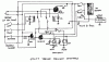
The above picture is showing the rear breakout card, designed to replace the minimal PCB and batteries inside a over-the-counter bicycle rear light housing. (point 5 in the below picture)
Everything is designed around the 4-wire "bikebus", a i2c-bus with my own name, for no apparent reason.
The bikebus is 5+v, gnd, sda and scl, and the idea is to have the bikebus in a star-configuration, the center-hub being the battery compartment.(point 2 in the below picture).
I threw together a picture to demonstrate my bike and to clarify the layout. ( sorry folks, just realized that the original jpg was mirrored..(CAD purposes))
The bikebus cable will run "like a Y", from point 2 to 5, splitting upwards to point 4 around where point 3 is.
Point 1 will wire directly into the main battery protoboard.

The above picture shows a version of the bike i have (mine has smaller front wheel), but the basics are the same.
The numbers on picture represents:
1: the front gear shifter mast; the location to fix my front lights.
2: the main battery compartment, inside the black tube.
3: the location for the on-button.
4: the handlebar "unit", consisting of the arduino nano headerless board, buttons and FET´s to control the front turn indicators, inside the rear view mirrors.
5: rear light housing, containing the rear i2c breakout box. This is also where the rear (moped) turn indicators are mounted.
At its current state, all the pin extender modules are completed, but not installed, the lights are all modified exept the front extra light (missing a transistor over its ON-button (modeselect, click once for on, next click steps up light output until mode3=full output).
The handlebar unit is also missing (had to scrap the pcb), so im going to build a bare essentials-protoboard, housing the arduino, condensators (button debounce) and front turn indicator FET´s.
Its going to be tight, i have roughtly 19x150mm space to work in, inside a tube.
I ordered waterproof tactile buttons, that will be discretely installed around the brake lever base on both sides that will toggle each function, they will then be covered with tape to keep them in place and hidden.
The brake levers will also be modified, a brake sensor will be installed in each, like shown in the link below:
https://www.avdweb.nl/solar-bike/mechanical-issues/brake-switch.html
And since i will be using internal wiring, a single hole next to each brake lever will let all the leads out, in a (hopefully) neat little (taped) cable, tucked away inside the brake lever body.
Over the coming weeks (while i wait 6-8 weeks for my online purchases) i will be completing the handlebar unit.
I already have a working jumpered protoboard, so its just the matter of minaturizing the circuit and solder it together.
In other words; the project is "nearly" complete, its just lacking the final ingredients, the power module.
The idea is to use a tactile button as a ON-"switch", then keep the system on via software, creating a software OFF, so i dont have to remember turning it off after use.
The link below shows the circuit im planning on using, with the difference that i will be using 2s lipo, 7,4v (or similar li-ion eventually)
https://homecircuits.eu/blog/arduino-low-voltage-disconnect-circuit/
https://homecircuits.eu/blog/arduino-low-voltage-disconnect-circuit/
I have a couple of those cheap voltage regulator PCB´s from ebay, the one with a blue box that has a flathead screw on top, to regulate output voltage.
..I bought them years ago, so their names and exact specs are details of memories past..
But they did have input up to around 20 or 30 volts or so, converting them down to between 3v(or so?) and a number somewhat lower than input voltage.
The main battery board (protoboard with thruhole parts soldered with wires) will also hold the front i2c pin expander, that will control the system-ON FET as well as the front lights via FET´s
The front lights are plural, triple to be precise, where the position light, low beam, is a somewhat weak bicycle light, and the extra light, rally light or high beam (call it what?) is a dual LED cree xm-l t6 high-output light, with its own in-house LEDdriver.
I have ordered a whole bunch of ebay stuff over the past few days, battery monitoring circuits and temperature gauges, BLE-modules and so on, so it feels somewhat moot to try to build the power protoboard before they arrive..
But here´s a list of things that must be on the main power board:
MCP23008, 8-p pin extender (only a few pins used).
Battery input terminal (6-18ish volts)
Connector for "bikebus" cable
PullUp resistors for the i2c bus.
Stuff for the front lights;
2x FET´s, power breakers, one for each front light unit (the dual extralights body still counts as 1)
connectors for the cables to the front lights and the modeSelect transistor (soldered over the original ON button inside the extralight housing).
and stuff for the auto-off circuit:
optocoupler (FOD817B)
FET, main switch ( IRFZ24N, TO-220 )
The "extras":
INA226 Power monitoring module**broken link removed**
LM75A temperature sensors (battery compartment monitoring)
AT24C32, DS1307 RealTime Clock module
HM10-cc2540 BLE module
I will eventually connect other realWorld sensors to the project, probably using i2c bus to wire them up, but i still havent found ways to add these to the project.
They are primarily hall effect scmitt-triggers for the rotational counters (speed, cadence), but i havent found a way to interrupt via i2c yet (arduino IDE) so i would be forced to use a dedicated cable, all the way up to the handlebar if i´dd try to add these feature now..
And im NOT going back to the old (and removed) crows-nest, with vga-, cat5- and dual lead- cables all over my bike...
i´dd rather skip these features, adding them via gps/glonas instead.
Now i just have to figure out how to wire it all together, but in a neat and SAFE way...
And as a final note:
I always appreciate feedback and i can take a "youre an idiot, you cant do it like that", as long as its followed by "because of this".
I sometimes fail to read the correct emotional value behind a certain way of writing, like irony or perhaps misreading constructive criticism as something else, but in the end, i always appreciate the content of the feedback.
And yes, im Autistic.
..and sorry about the wall of text, this is by far my largest project ever, in every way except physical size.
I learn by doing, so the best way for me to learn programming and electronics is to define a goal, then try my bestest to find a way to reach it.
I need somewhere to house my build-blog, and figured you guys might appreciate it, if for nothing else, for shits ´n giggles..
This is the main project thread; initial post is all about the current state of things, primarily hardware and will be updated as the build progresses.
This may cause some confusion regarding the chronology of things, stuff gets deleted or changed, but i believe its the easiest way to maintain a easily understandable current state of things for the readers.
I will also be using this thread (specifically its initial post) as a project organizer, keeping it in one place while letting others "monitor" the progress.
Hopefully this will lead to faster development, since its taken me about 2 years to finish version 1(crowsnest of cables) and about a year in developing version 2 (i2c), still not completed.
The goal with the BikeLightProject is, as its name implies, a bike (or vehicle) light controller that will eventually also handle realworld measurements, like speed, heartrate and cadence (pedal cranks rpm).
The route i selected for the Version 2 (current) is I2C-based pin extenders, placed at strategic locations, then connect the vehicle lights to the pin extender breakout boards (n-channel fets).
I designed and ordered custom PCB´s from china (first attempt!) and populated them myself.
Most of them worked out allright, some with small "adjustments", while others had to be scrapped due to designer incompetence..
In case anyone would care to take a looksie, the project is at easyEDA.com so if youre a member(free), drop me a message and i´ll share the project with you.
The above picture is showing the rear breakout card, designed to replace the minimal PCB and batteries inside a over-the-counter bicycle rear light housing. (point 5 in the below picture)
Everything is designed around the 4-wire "bikebus", a i2c-bus with my own name, for no apparent reason.
The bikebus is 5+v, gnd, sda and scl, and the idea is to have the bikebus in a star-configuration, the center-hub being the battery compartment.(point 2 in the below picture).
I threw together a picture to demonstrate my bike and to clarify the layout. ( sorry folks, just realized that the original jpg was mirrored..(CAD purposes))
The bikebus cable will run "like a Y", from point 2 to 5, splitting upwards to point 4 around where point 3 is.
Point 1 will wire directly into the main battery protoboard.
The above picture shows a version of the bike i have (mine has smaller front wheel), but the basics are the same.
The numbers on picture represents:
1: the front gear shifter mast; the location to fix my front lights.
2: the main battery compartment, inside the black tube.
3: the location for the on-button.
4: the handlebar "unit", consisting of the arduino nano headerless board, buttons and FET´s to control the front turn indicators, inside the rear view mirrors.
5: rear light housing, containing the rear i2c breakout box. This is also where the rear (moped) turn indicators are mounted.
At its current state, all the pin extender modules are completed, but not installed, the lights are all modified exept the front extra light (missing a transistor over its ON-button (modeselect, click once for on, next click steps up light output until mode3=full output).
The handlebar unit is also missing (had to scrap the pcb), so im going to build a bare essentials-protoboard, housing the arduino, condensators (button debounce) and front turn indicator FET´s.
Its going to be tight, i have roughtly 19x150mm space to work in, inside a tube.
I ordered waterproof tactile buttons, that will be discretely installed around the brake lever base on both sides that will toggle each function, they will then be covered with tape to keep them in place and hidden.
The brake levers will also be modified, a brake sensor will be installed in each, like shown in the link below:
https://www.avdweb.nl/solar-bike/mechanical-issues/brake-switch.html
And since i will be using internal wiring, a single hole next to each brake lever will let all the leads out, in a (hopefully) neat little (taped) cable, tucked away inside the brake lever body.
Over the coming weeks (while i wait 6-8 weeks for my online purchases) i will be completing the handlebar unit.
I already have a working jumpered protoboard, so its just the matter of minaturizing the circuit and solder it together.
In other words; the project is "nearly" complete, its just lacking the final ingredients, the power module.
The idea is to use a tactile button as a ON-"switch", then keep the system on via software, creating a software OFF, so i dont have to remember turning it off after use.
The link below shows the circuit im planning on using, with the difference that i will be using 2s lipo, 7,4v (or similar li-ion eventually)
https://homecircuits.eu/blog/arduino-low-voltage-disconnect-circuit/
https://homecircuits.eu/blog/arduino-low-voltage-disconnect-circuit/
I have a couple of those cheap voltage regulator PCB´s from ebay, the one with a blue box that has a flathead screw on top, to regulate output voltage.
..I bought them years ago, so their names and exact specs are details of memories past..
But they did have input up to around 20 or 30 volts or so, converting them down to between 3v(or so?) and a number somewhat lower than input voltage.
The main battery board (protoboard with thruhole parts soldered with wires) will also hold the front i2c pin expander, that will control the system-ON FET as well as the front lights via FET´s
The front lights are plural, triple to be precise, where the position light, low beam, is a somewhat weak bicycle light, and the extra light, rally light or high beam (call it what?) is a dual LED cree xm-l t6 high-output light, with its own in-house LEDdriver.
I have ordered a whole bunch of ebay stuff over the past few days, battery monitoring circuits and temperature gauges, BLE-modules and so on, so it feels somewhat moot to try to build the power protoboard before they arrive..
But here´s a list of things that must be on the main power board:
MCP23008, 8-p pin extender (only a few pins used).
Battery input terminal (6-18ish volts)
Connector for "bikebus" cable
PullUp resistors for the i2c bus.
Stuff for the front lights;
2x FET´s, power breakers, one for each front light unit (the dual extralights body still counts as 1)
connectors for the cables to the front lights and the modeSelect transistor (soldered over the original ON button inside the extralight housing).
and stuff for the auto-off circuit:
optocoupler (FOD817B)
FET, main switch ( IRFZ24N, TO-220 )
The "extras":
INA226 Power monitoring module**broken link removed**
LM75A temperature sensors (battery compartment monitoring)
AT24C32, DS1307 RealTime Clock module
HM10-cc2540 BLE module
I will eventually connect other realWorld sensors to the project, probably using i2c bus to wire them up, but i still havent found ways to add these to the project.
They are primarily hall effect scmitt-triggers for the rotational counters (speed, cadence), but i havent found a way to interrupt via i2c yet (arduino IDE) so i would be forced to use a dedicated cable, all the way up to the handlebar if i´dd try to add these feature now..
And im NOT going back to the old (and removed) crows-nest, with vga-, cat5- and dual lead- cables all over my bike...
i´dd rather skip these features, adding them via gps/glonas instead.
Now i just have to figure out how to wire it all together, but in a neat and SAFE way...
And as a final note:
I always appreciate feedback and i can take a "youre an idiot, you cant do it like that", as long as its followed by "because of this".
I sometimes fail to read the correct emotional value behind a certain way of writing, like irony or perhaps misreading constructive criticism as something else, but in the end, i always appreciate the content of the feedback.
And yes, im Autistic.
..and sorry about the wall of text, this is by far my largest project ever, in every way except physical size.